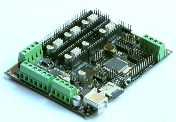
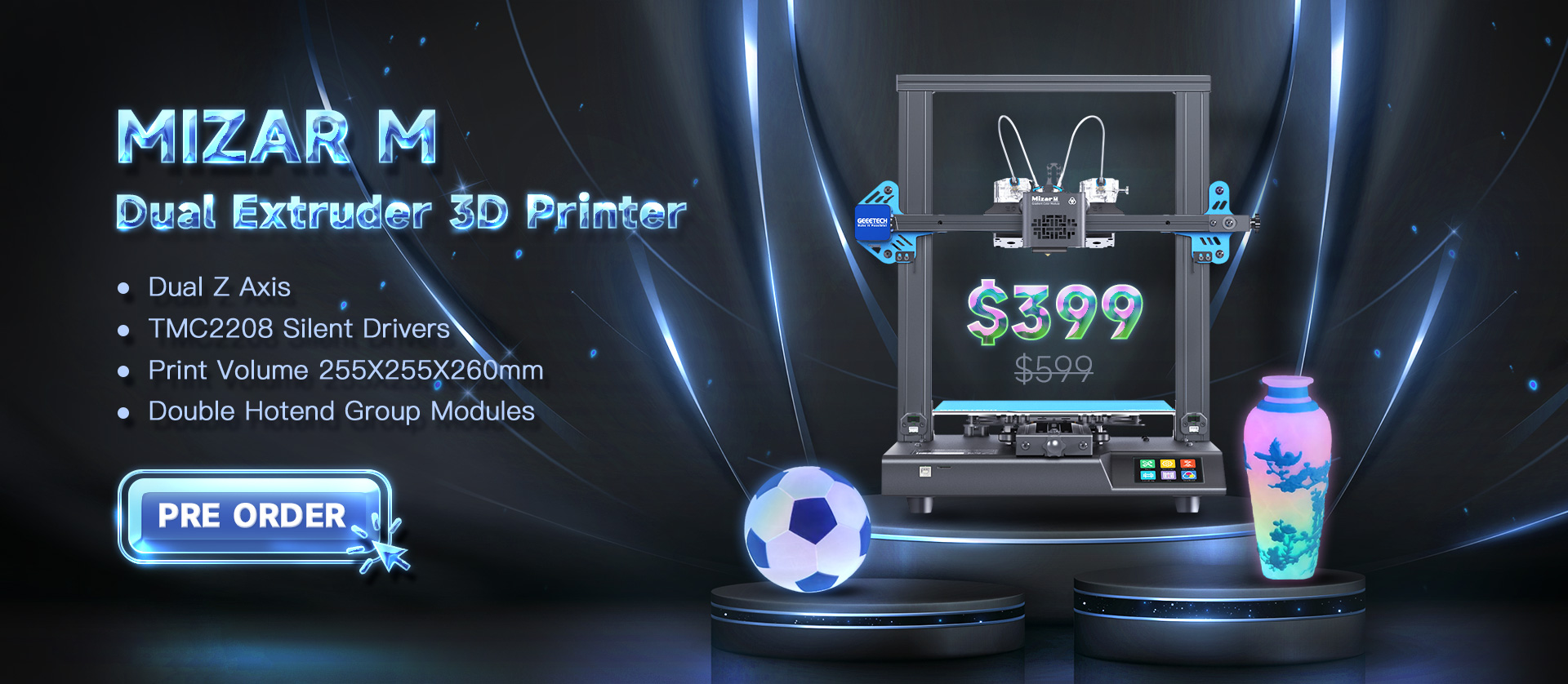
Today we have a new product — Megatronics Board. RAMPS is likable and gained many users of 3D printers, after using it for a long time, there are some aspects of the board however that make it unusable for future electronics. To avoid the complex wires, the Megatronics is a single-board solution combining the Arduino MEGA and RAMPS boards which is based on many famous open-source products including Arduino Mega 2560, RAMPS, and SD Ramps. It combines all the major features of these boards into a single-board solution for more reliable 3D printing.
Megatronics has a powerful Atmega2560 processor with 256 kB memory, running at 16 MHz. The board can be connected to a PC using a normal USB cable. It will register as an FTDI FT232R device. The board is compatible with the Arduino Mega 2560 and will therefore be easily programmed from the Arduino IDE.

The board is supplied with Marlin firmware. If you want to upload another firmware, you can use Arduino IDE to upload firmware to the Megatronics board. Under Linux select as board ‘Arduino Mega 2560 or Mega ADK’. Under other operating systems, the USB will not be reset correctly and you will need to adjust the boards.txt. Restart Arduino IDE and select Mechatronics as a board. You should be able to upload it correctly now.
Before using it, it’s necessary to test the functionality of the board by testing firmware. After doing this, you can set up your project.
Here is a picture of a basic setup from the RepRap wiki. Maybe you have different requirements, if you can join our forum or leave them in the comments section below to discuss with us about it.


We have the RepRap Megatronics controller board 2560.
We want to connect the LCD and key-pad to the board. The problem is that the key-pad connector is 10 pin and the LCD connector is 12 pin on the controller 2560 and can be seen in the photos on the web. The ribbon connector from the key-pad/LCD are both 10 pin each. How do we connect the 10 pin to the 12 pin on the PCB when all the adapters are 10 pin. Where do I find a 12 pin adapter to 10 pin without cutting off 2 pins?
We want to do this correctly and would like to implement this into a product
hi Don, good news, you don’t need to find a 12 pin connector, just leave the last 2 pins on the LCD connector alone, that works the same.
Comments are closed.