Yesterday we have finished all machine part, did you learn them?Today let’s go on with electric part.
13 Mount the control board
GT2560
Before you start wiring, please take a look at the wiring schematics.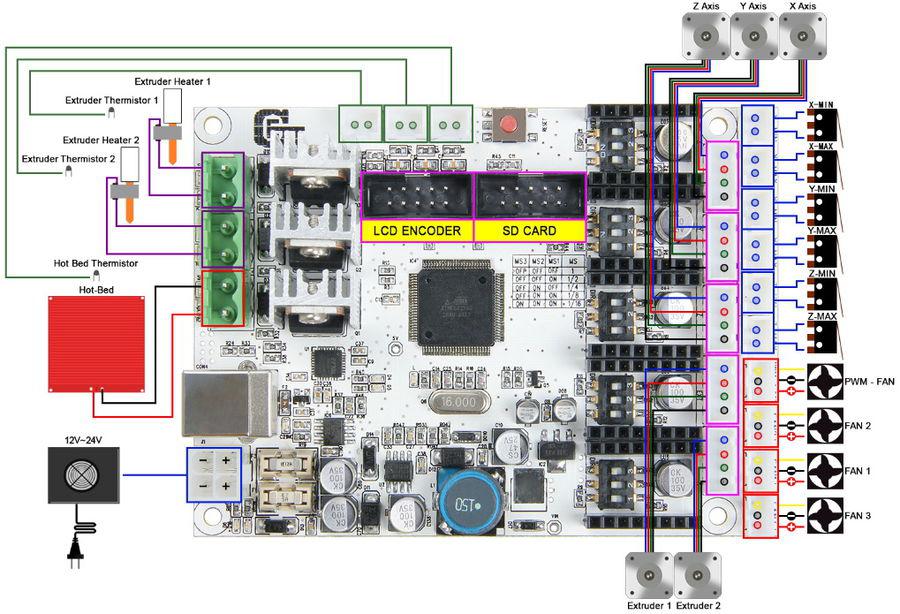
You can see original picture here.
There is one thing you need to note that the extruder number in this picture is 1 and 2, but in the following steps, I referred them as 0 and 1 correspondingly.
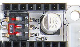
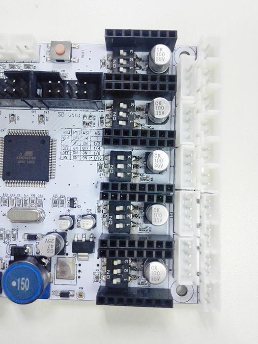
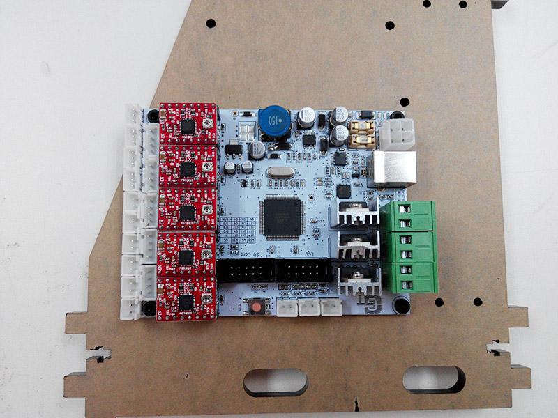
Step1. The subdivision of stepper motor can be setup by dial switch, turn on all the dial switch
Step2. Plug the 5 A4988 into the stepper motor driver slot. Mind the directions of A4988.
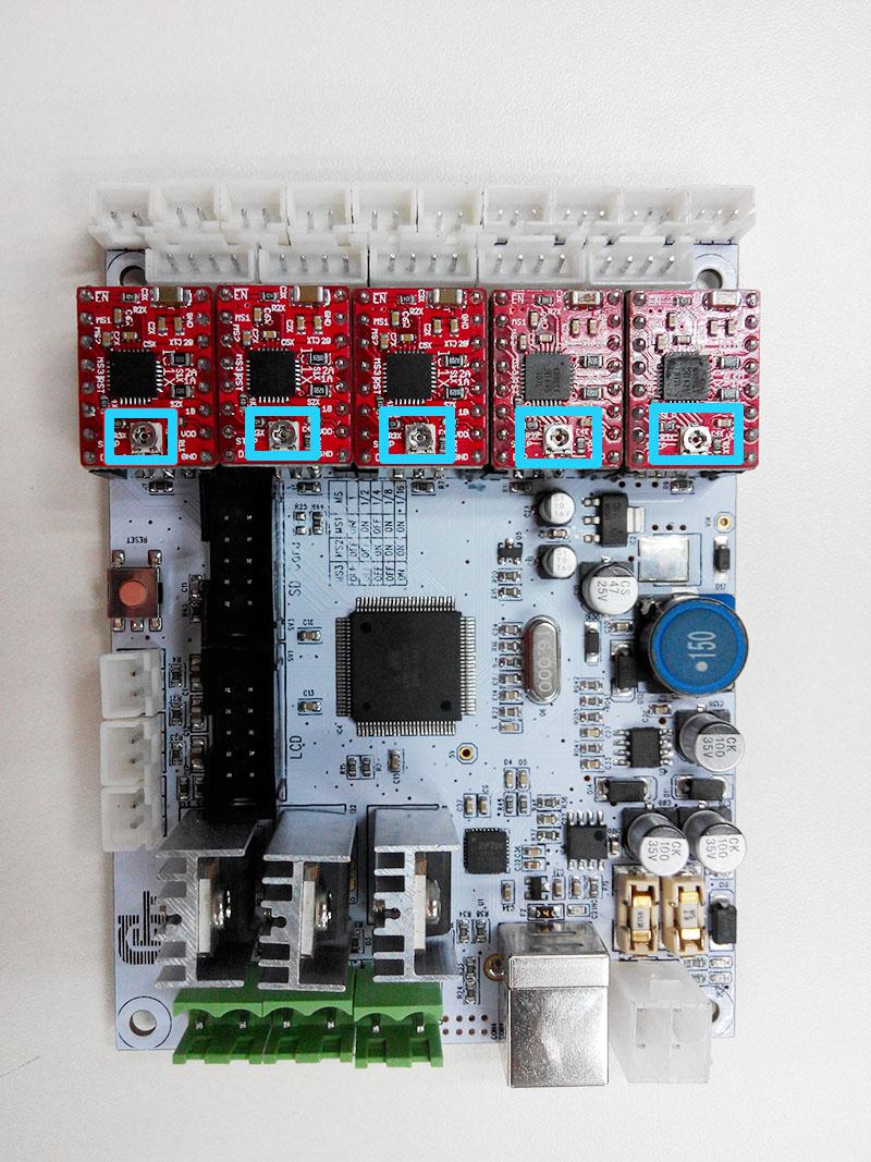
If you are using DRV8825 instead of A4988, The correct connections are as follow:
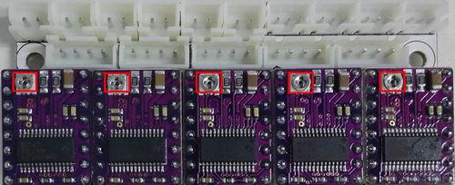
For your convenience, the above two steps is finished by us. you can skip them.
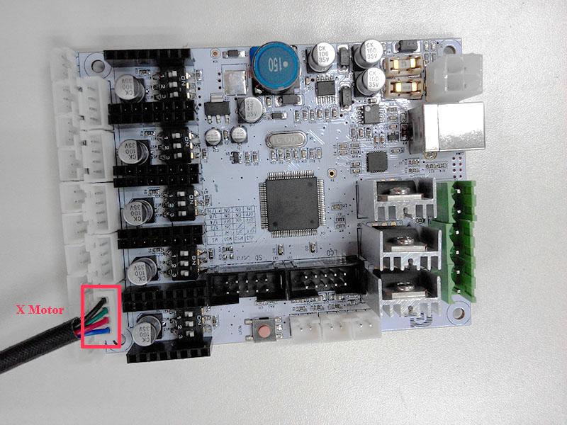
Step3. Connect wires for motors.
1) Connect wires for X-axis motor.
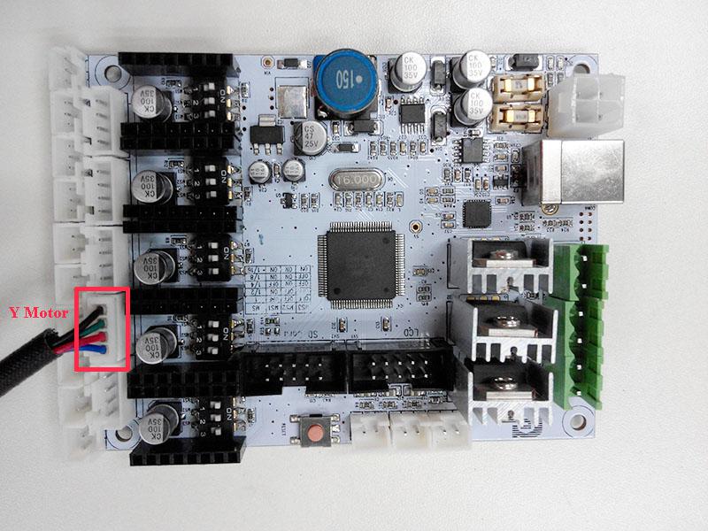
2) Connect wires for Y-axis motor.
3) Connect wires for Z-axis motor.
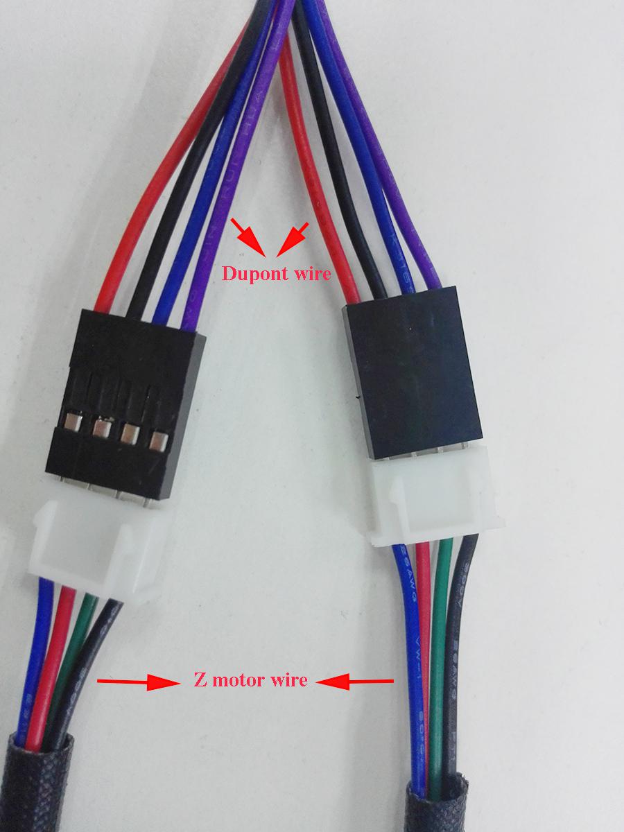
Here you need to use the DuPont wire (NO.64).
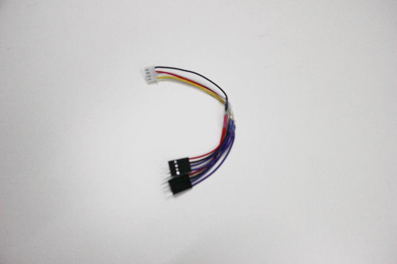
Plug the end with one terminal into the Z motor slot. And connect the two wires of Z motor with the two DuPont wires separately.
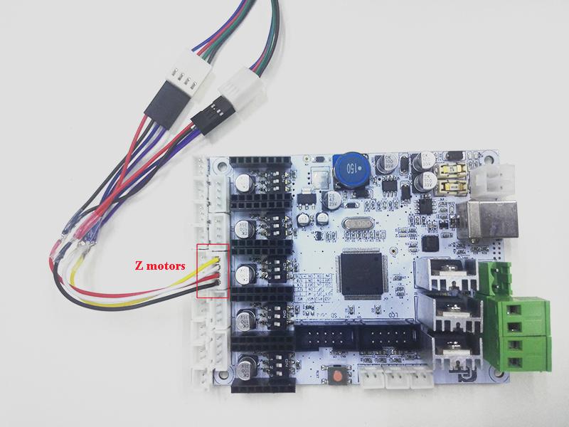
Note the color of the connection as below:
|
DuPont wires |
Motor wire |
|
Red |
Blue |
|
Black |
Red |
|
Blue |
Green |
|
Purple |
Black |
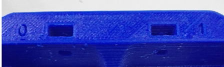
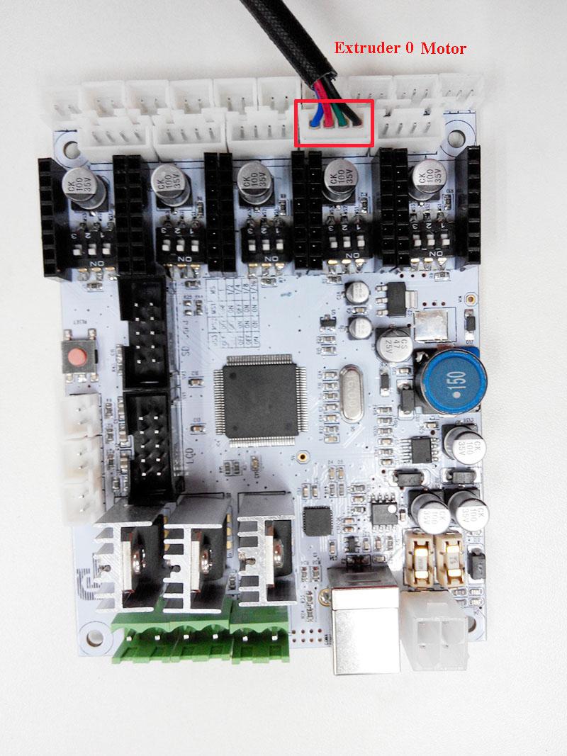
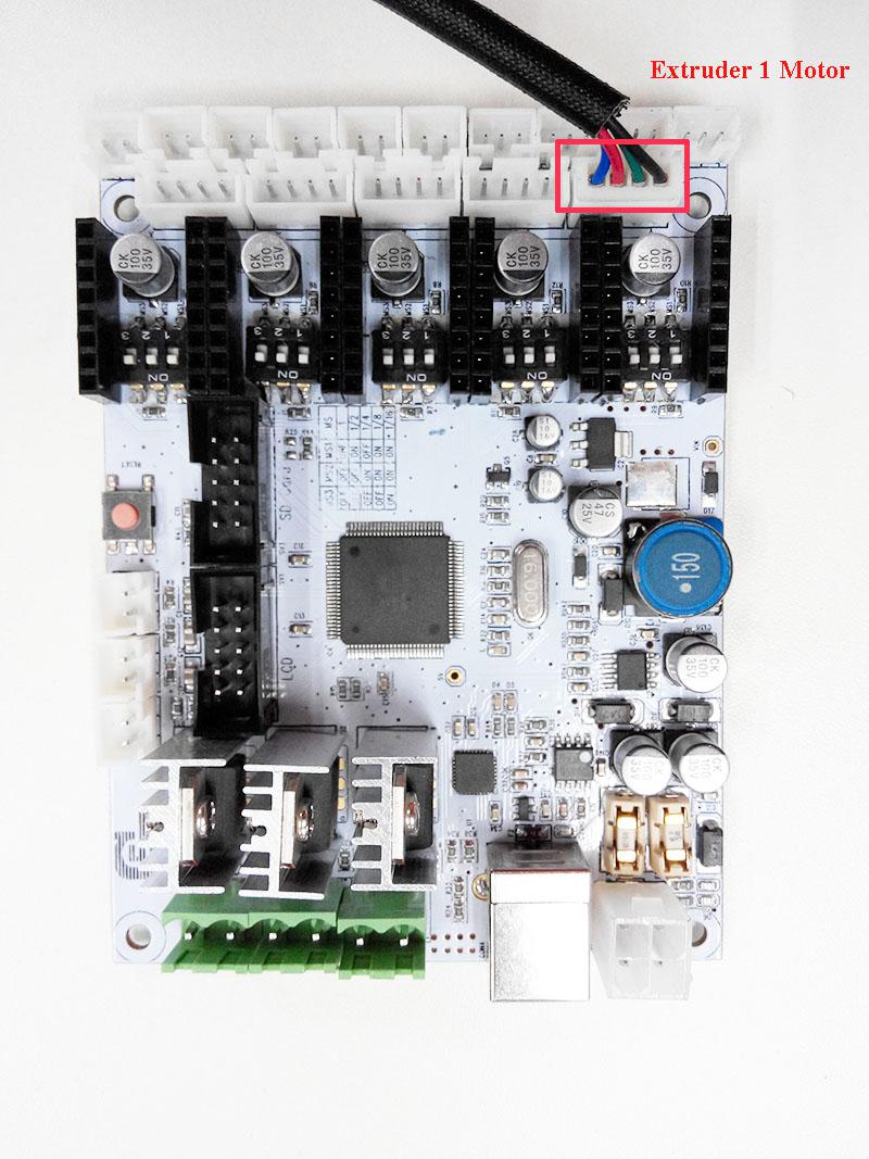
4) Connect Extruders
As you can see 0 and 1 from the extruder holder [NO.P4], you need to straighten out the two wires and do not mix them up.
Connect extruder 0.
Connect extruder 1.
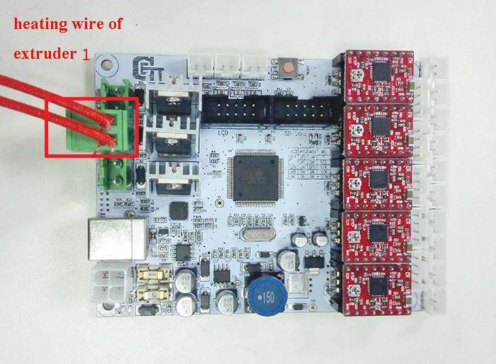
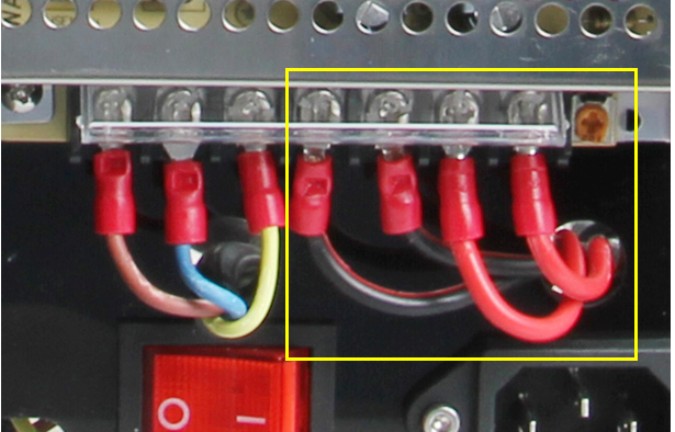
Step4. Connect heating wires.
Loosed the screws in the green terminal and put the red wires into the slot and screw it up.
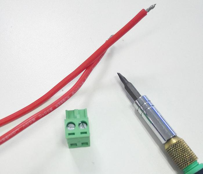
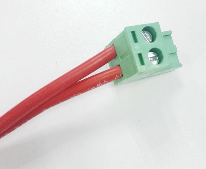
* There is no “+” and “-“for heating wires
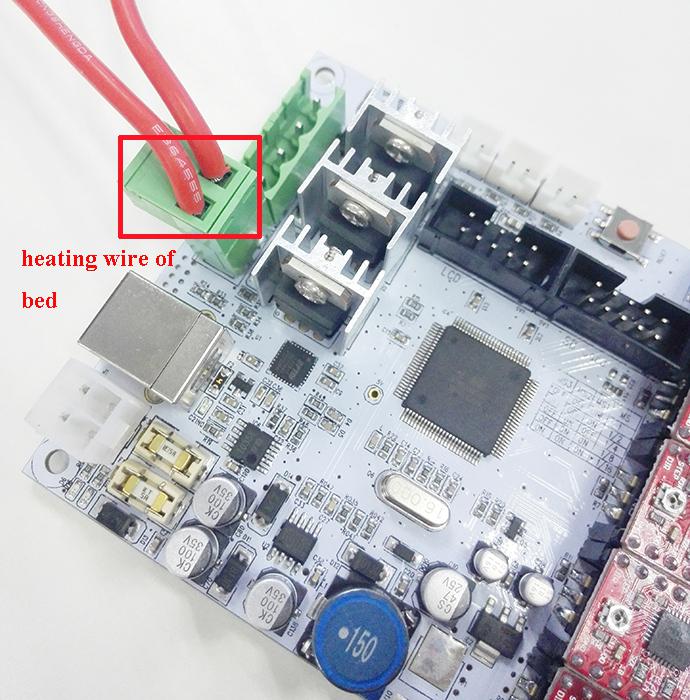
1) Connect heating wires for heatbed.
2) Connect heating wires for extruder 0.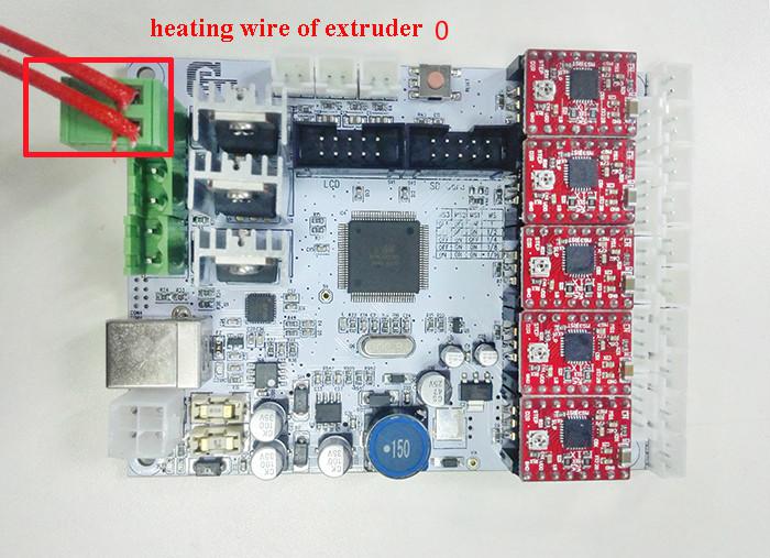
3) Connect heating wires for extruder 1.
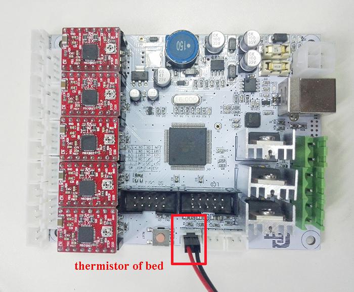
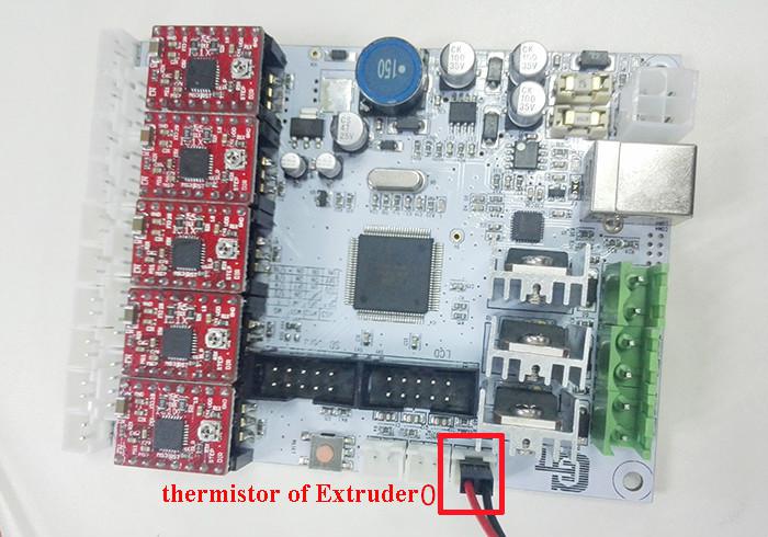
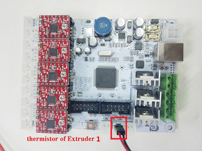
Step4. Connect wires for thermistor.
1) Connect wires for thermistor of heatbed.
2) Connect wires for thermistor of extruder 0.
3) Connect wires for thermistor of extruder 1.
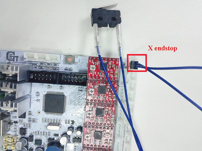
Step5. Connect wires for endstop.
* There is no “+” and “-“for endstop
1) Connect wires for endstop of X-axis at X-Min.
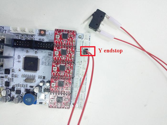
2) Connect wires for endstop of Y-axis at Y-Min.
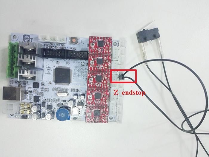
3) Connect wires for endstop of Z-axis at Z-Min.
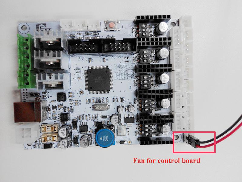
Step6. Connect wires for Fan.
1) Connect fan for control board at FAN3.
Note the “+” and “-“for fan
Red: +
Black: –
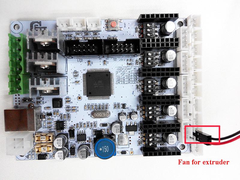
2) Connect fan for extruder at FAN1.
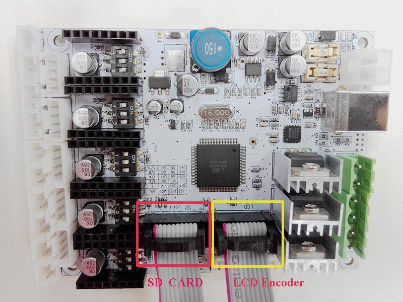
Step7. Connect wires for LCD panel.
There are two cables, one is for LCD encoder, the other is for SD card, do not connect them reversed
Step8. Connect wires for power input.
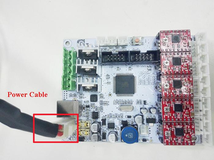
Plug the other end into the PSU.
That is all for the wiring of GT2560.
14 Mount the board
|
Required number |
Required parts |
|
1 |
Control board |
|
4 |
M3 x 16 screw |
|
4 |
M3 nut |
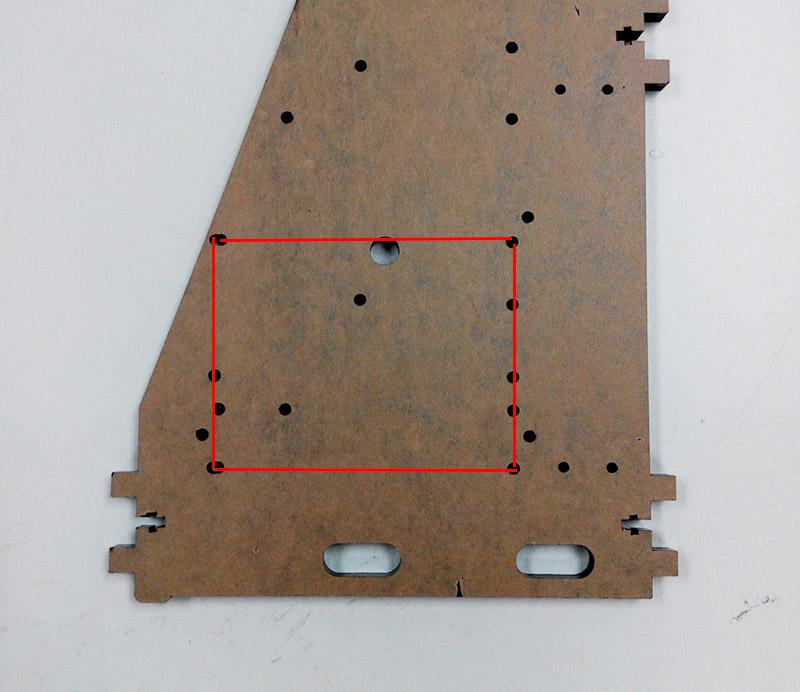
Mount the board on the left side panel of the printer. You can see the locating hole as shown in the following picture. Screw it up with M3 x 16 screws and nuts.
Please pay attention to the direction of the board, the end with Capacitor should be mounted towards the fan for better heat dissipation.
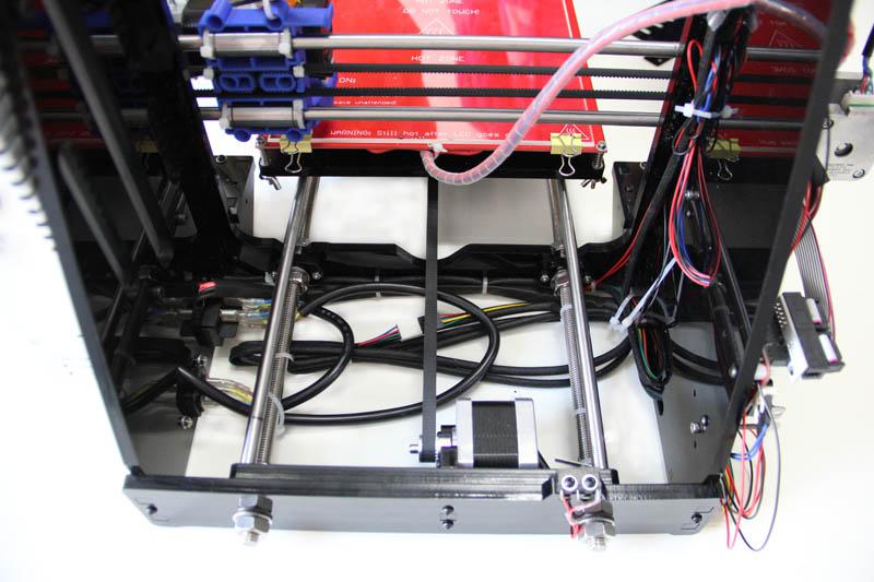
15 Tidy out the wires.
Use the wire coil to tie put those wires together. There are holes on the acrylic plates for the wires, you can arrange them as you like.
16 Mount the filament spool.
|
Required number |
Required parts |
|
3 |
Filament side panel |
|
4 |
M3 x 16 screw |
|
4 |
M3 square nut |
|
2 |
PVC tube |
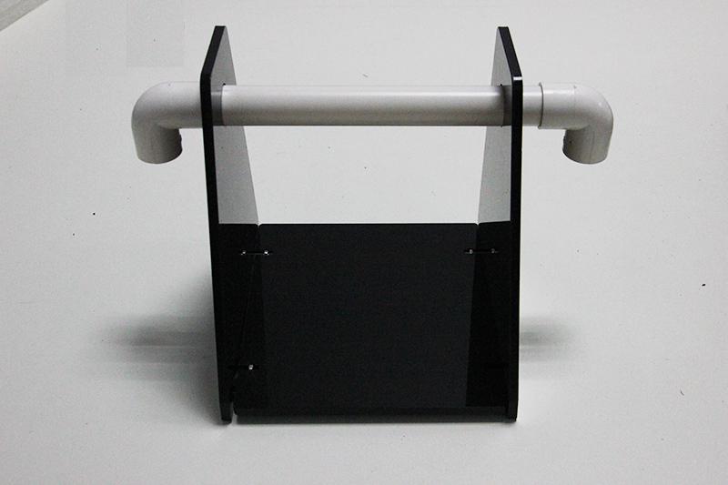
The whole printer assembly work is already done.
Hope you enjoy the whole process.
for more detailed introduction of Geeetech prusa I3, please refer to geeetech online store.