As last time ,we have finished the Yaxis part,today we will go on with all machine part.
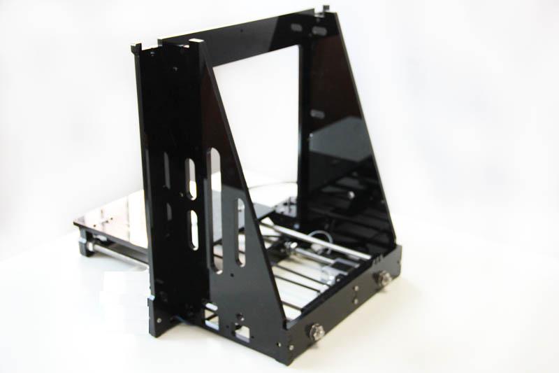
3 Assemble Y – Z axis
|
Required number |
Required parts |
|
1 |
X-Z frame |
|
4 |
M3 x 20 screw |
|
4 |
M3 nut |
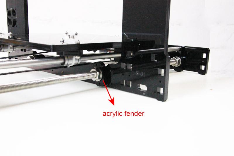
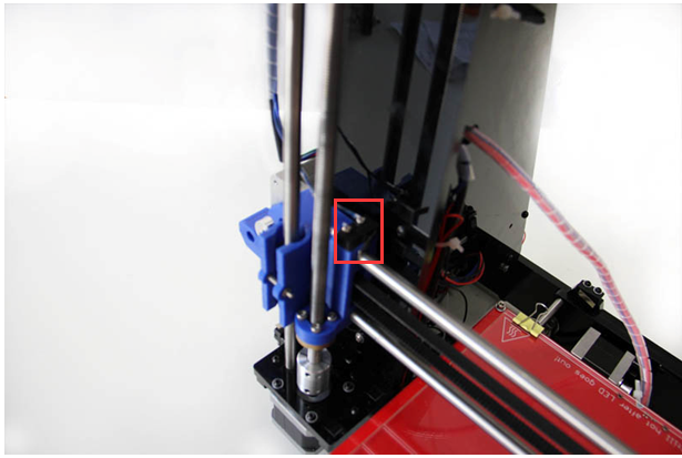
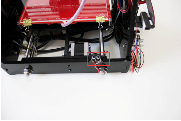
Step1. Held upright the main frame is after the acrylic fender washers on the threaded rods. Here you can use the A2 panel as a reference to measure the distance A1 and A12 (the rear plate).
Step2. Screw up the main frame to the acrylic fender with M3 x 20 screws.
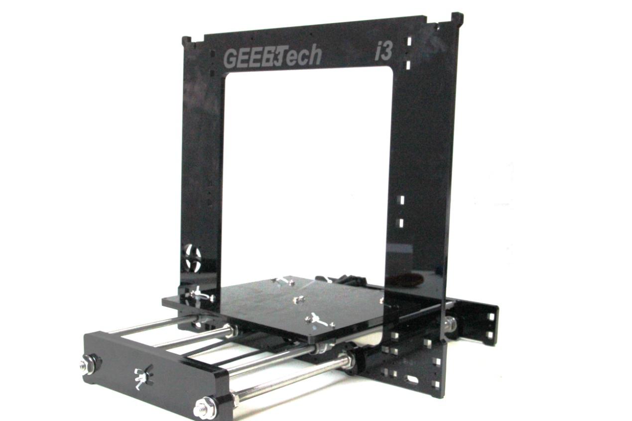
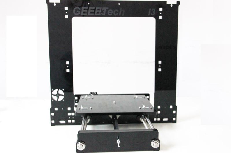
Step3. Screw up the M10 screw on the threaded rod of Y-axis. You can see the finished picture.
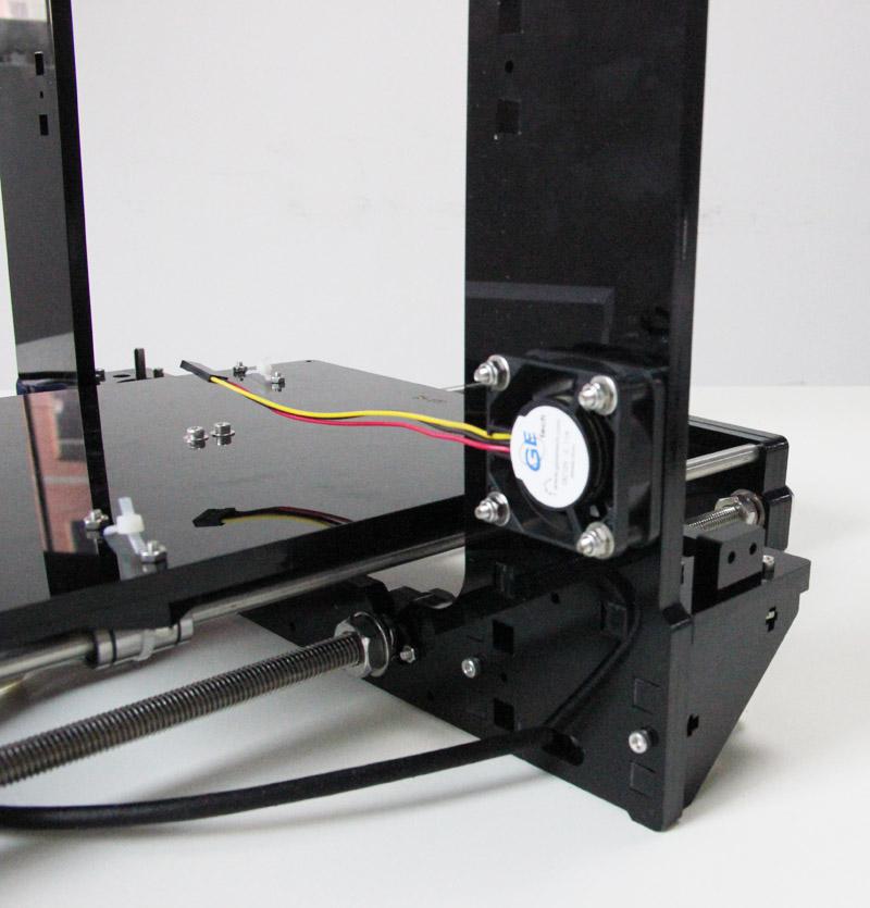
4 Mount the fan
|
Required number |
Required parts |
|
1 |
Fan |
|
4 |
M3 x 30 screw |
|
4 |
M3 locknut |
5 Assemble the right and left side panel
|
Required number |
Required parts |
|
1 |
Acrylic left frame |
|
1 |
Acrylic right frame |
|
8 |
M3 x 16 screw |
|
8 |
M3 square nut |
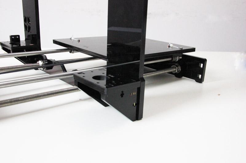
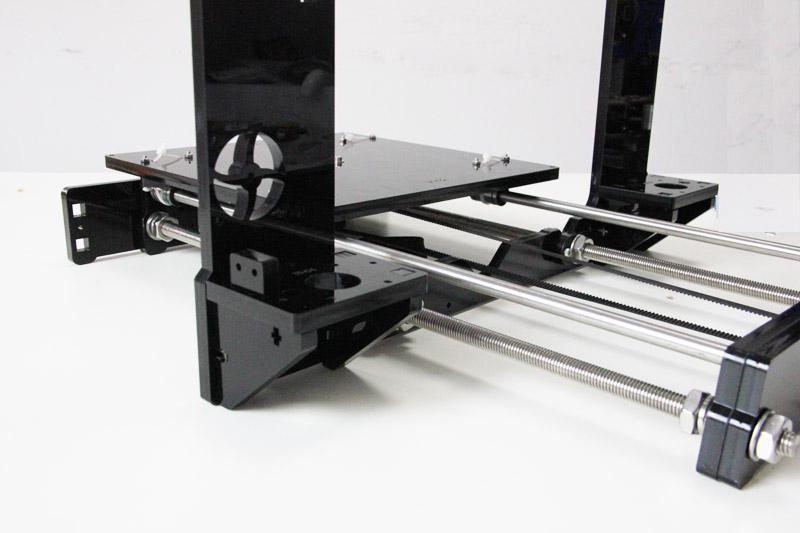
Step1. Screw up the X-Z frame and the side panel then connect the rear part of the Y axis and the side panel together. You may need to adjust the distance of the X-Z frame to the rear plate.
All you need here is M3 x 16 screws and M3 square nuts.
6 Assemble the Z axis (the vertical axis)
6.1 Assemble the Z-axis bottom mount
|
Required number |
Required parts |
|
2 |
Z Motor fixed plate |
|
4 |
Z Motor support plate |
|
10 |
M3 x 16 screw |
|
10 |
M3 square nut |
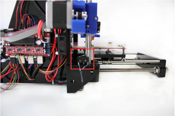
Step1. It would be easier to mount the A4/A5 to A6 and A7 first, and then mount the assembled part to A1.
Step2.Screw up the acrylic plates with M3 x 16 screws and M3 square nuts.
*The right and left bottom mount are different; the left one has a mount for the Z end stop. Please look at the following picture.
6.2 Assemble the 2 Z motors
|
Required number |
Required parts |
|
2 |
Stepper Motor |
|
8 |
M3 x 12screw |
Step1.Thread the wires of the motors through the holes
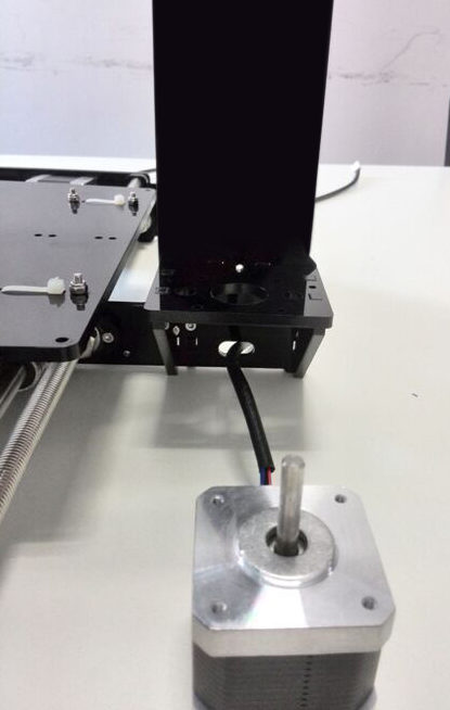
Step2. Screw up the motors with 4 M3 x 12 screws. Do the same with the other Z
motor.
7 Assemble the X axis (the horizontal axis)
7.1 Assemble the smooth rods.
|
Required number |
Required parts |
|
2 |
370mm smooth rod |
|
2 |
LM8UU linear bearing |
Slide the two bearings into the two rods respectively.
7.2 Assemble the X-Axis Idler
|
Required number |
Required parts |
|
2 |
624ZZ Ball bearing |
|
1 |
Bearing holder |
|
1 |
M3 X30 screw |
|
1 |
M4 X25 screw |
|
1 |
M4 locknut |
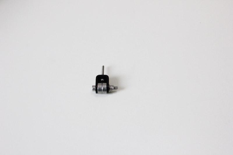
Step1. Put the screw through the Y bearing holder.
Step2. Thread the M4 x 25 screw through the holder with the 624ZZ bearings in between. Lock the other end of a M4 nut.
7.3 Assemble the X-Axis end
|
Required number |
Required parts |
|
1 |
X-axis left end |
|
1 |
X-axis right end |
|
2 |
LM8UU linear bearing |
|
1 |
M3 wing nut |
|
2 |
M3 x 16 screw |
|
2 |
M3 nut |
Step1. Mount the assembled idler into the right X-axis end. Here, you can insert the linear bearing into the end.
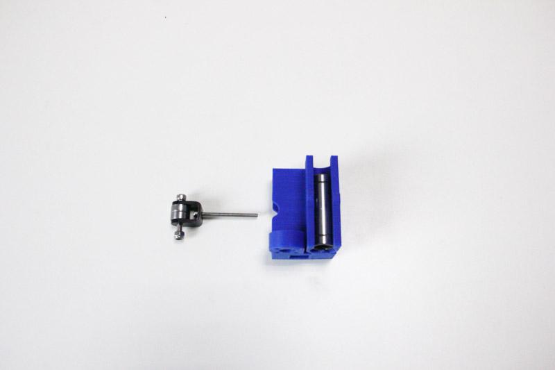
Step2. Lock it up tightly with a wing nut and insert a linear bearing into the slot. Pay attention to the direction of the idler. Please lock the M3X30 screw tightly in case any jam caused for the belt.
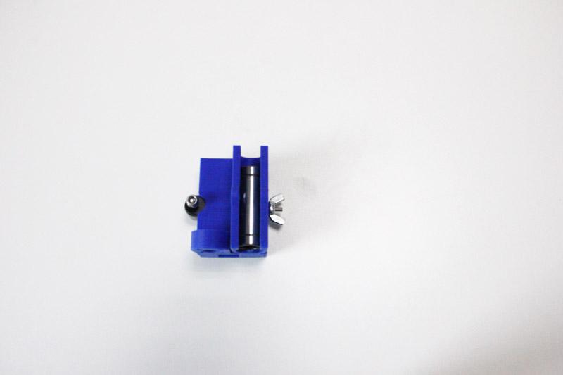
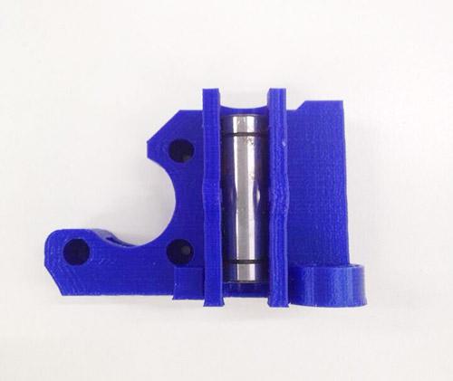
Step3. Insert another linear bearing into the slot of left end. Then lock the bearing with M3x 16 screw and nut. Do the same to the right end.
7.4 Assemble the X-axis rods and both ends
|
Required number |
Required parts |
|
2 |
Brass nut |
|
8 |
M3 x 16 screw |
|
1 |
M3 x50 screw |
|
1 |
M3 nut |
|
2 |
Screw locking ring |
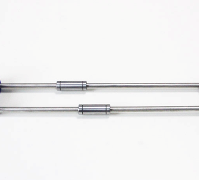
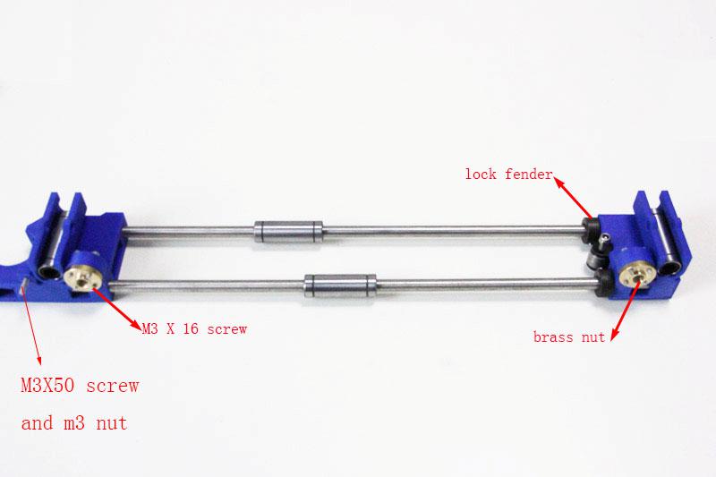
Step1. Thread the screw locking ring to both rods respectively. Screw them up
Step2. Thread the two rods into the two X-axis ends.
Step3. Mount the brass nut under both ends with 4 M3 x 16 screws for each.
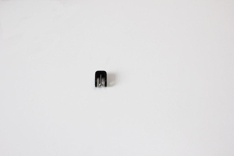
Step4. Fix the M3x 5 screw on left end. (This is for the Y end stop)
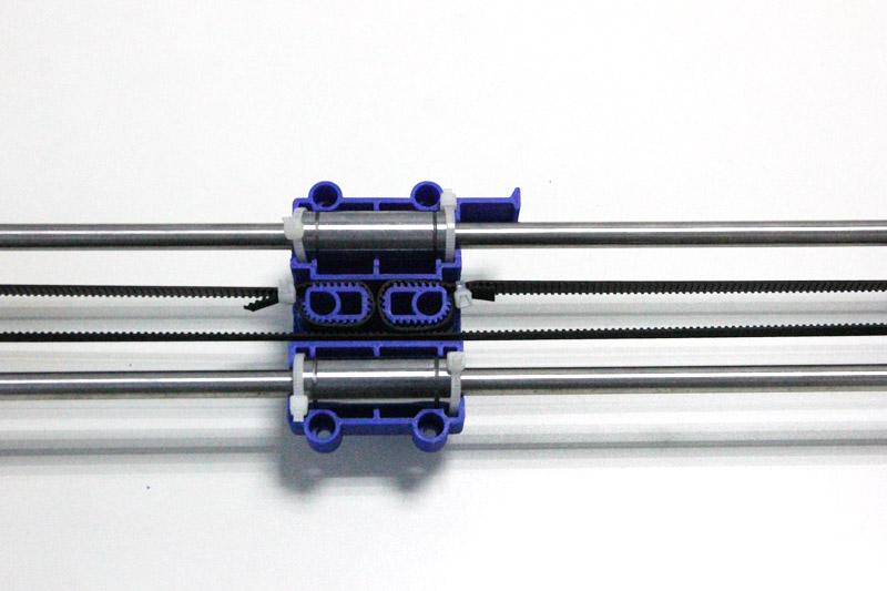
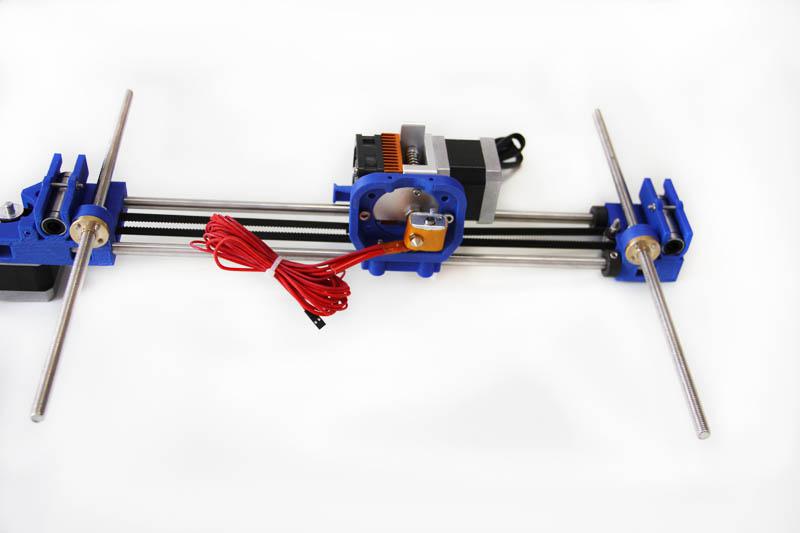
7.5 Mount the X-axis belt bracket on the smooth rods.
|
Required number |
Required parts |
|
1 |
print bracket |
|
4 |
Zip tie |
|
2 |
LM8UU linear bearing |
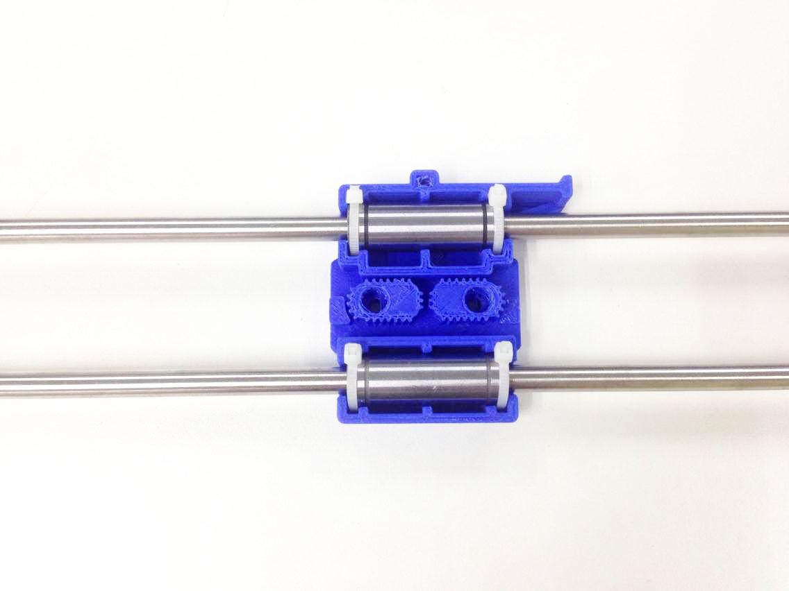
Step1. Mount the print bracket on the smooth rods.
1) Insert the linear bearings into the slot of the bracket as you can see from the picture.
2) Thread the zip-tie through the extruder bracket. Tie them up with zip ties.
* the stretching-out part is towards the Left end of X axis.
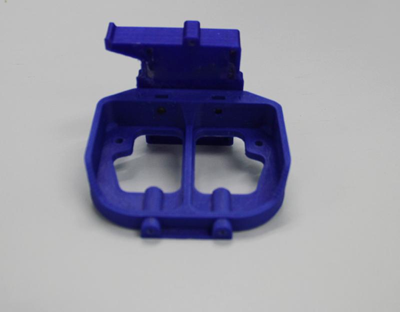
7.6 Mount the extruder holder.
|
Required number |
Required parts |
|
1 |
Extruder bracket |
|
2 |
M4 x 16screw |
|
2 |
M4 nut |
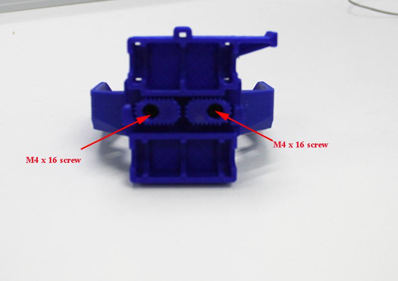
Step1. Put the 2 M4 nut into the hole, as shown in the picture.
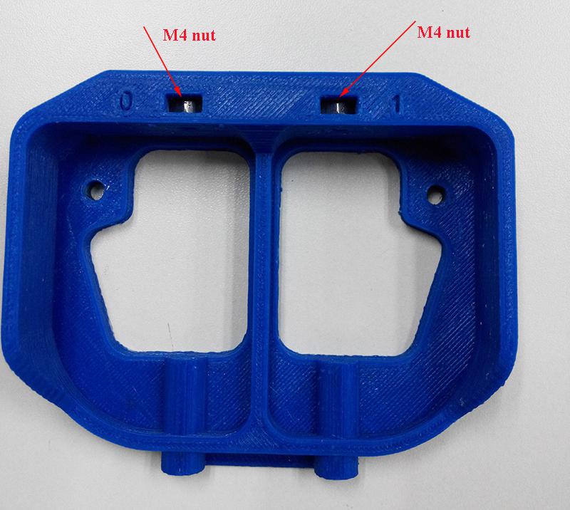
Step2. Screw up the belt bracket and the extruder support with two M4 x 16screws.
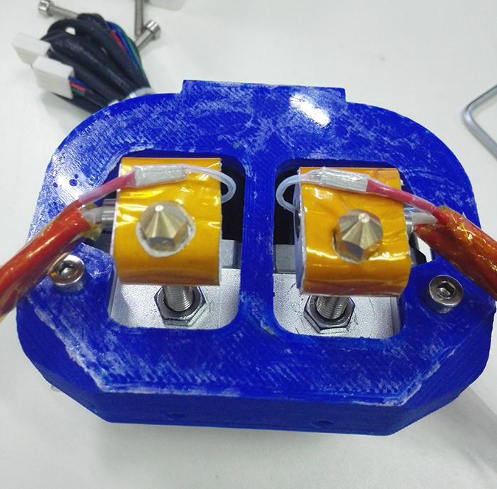
7.7 Mount the extruder
|
Required number |
Required parts |
|
1 |
MK8 dual extruder |
|
2 |
M4 x 12 screw |
|
2 |
M4 nut |
Step1. Mount the assembled extruder on the extruder support. Fix it up with two M4 x 12 screw and M4 nut.
Tips: keep the two nozzles flush.
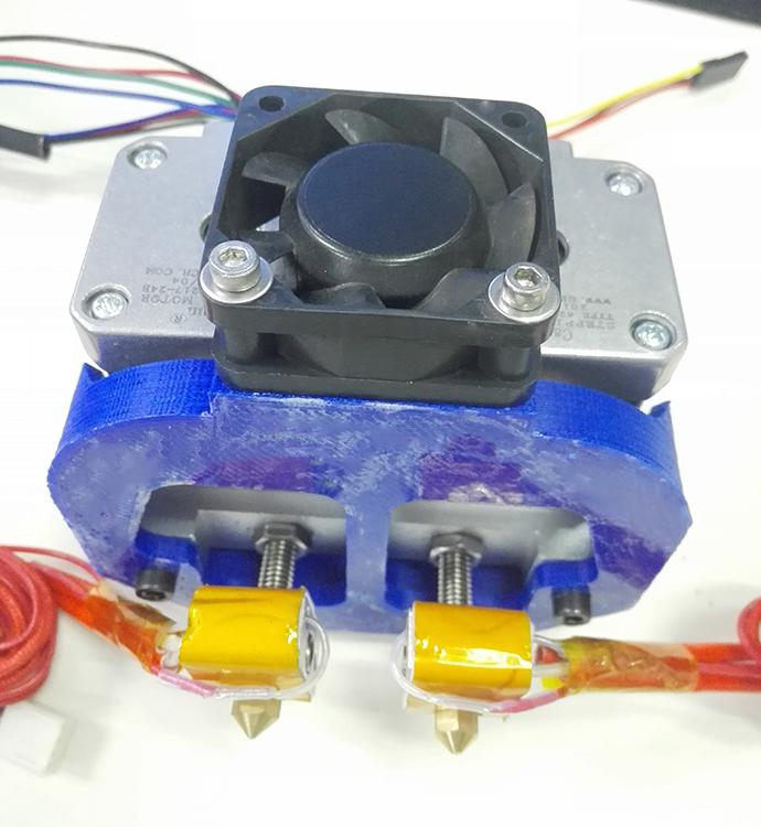
7.8 Mount the fan for extruder
|
Required number |
Required parts |
|
1 |
Fan |
|
2 |
M3 x 30 screw |
|
2 |
M3 washer |
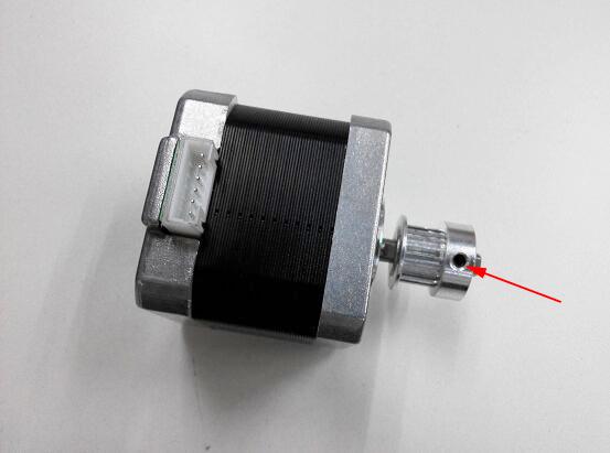
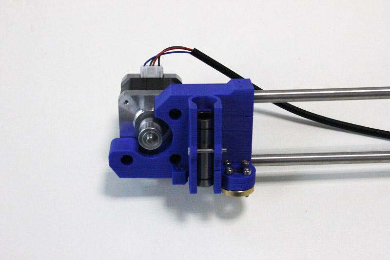
7.9 Mount the X-axis motor.
|
Required number |
Required parts |
|
1 |
Stepper motor |
|
1 |
Pulley |
|
3 |
M3 x 8 screw |
Please pay attention to the mount direction of the pulley, which is opposite to that of the Y-axis.
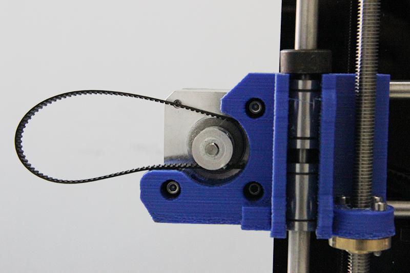
7.10 Amount the X-axis belt.
|
Required number |
Required parts |
|
1 |
Timing Belt |
|
2 |
Zip tie |
Step1. Thread the belt around pulley on the motor end.
(*The two linear bearings in the picture should be a longer one, please ignore it)
Step2. Another end of the belt should be threaded through the belt holder on the right end of the X-axis.
(The belt holder in the picture is different from yours, do not worry, it is ok for you to understand)
Step3. Insert the belt into the slot.
*Pay attention to the tooth mesh of the belt and that on the bracket. Tie up both ends tightly. (This bracket may be a bit different from yours, but it doesn’t matter)
In this step, when attach the second side of the timing belt for the x-axis, h you may not estimate accurately the length of the whole belt until the z-axis stage has been mounted. So, please do not rush to cut the extra belt, you need to re-adjust it later after the z-axis has been mounted.
8 Assemble the X-Z axis.
|
Required number |
Required parts |
|
2 |
Couplings |
|
2 |
L322 threaded rod |
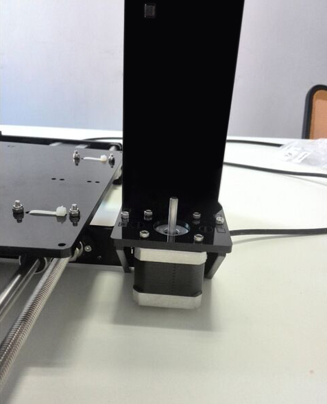
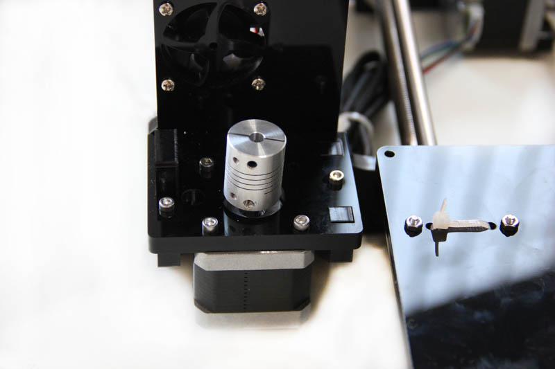
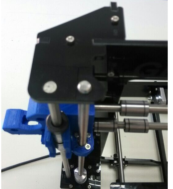
Step1. Fix the two couplings on both of the threaded rod. And plug it on the motor shaft.
*Mind the opening of the couplings, the larger opening should be connected to the threaded rods.
Step2. Thread the threaded rods of Z axis through the brass nuts. It would be easier to do it now. Keep both end of the X axis flush.
(Please ignore the MK8 extruder in this picture, if you are moving to this step, please send me a right picture with dual extruder, thanks.)
Step3. Put the assembled X-axis on the Z-axis. Then slide the smooth rod into the linear bearings.
(Please ignore the MK8 extruder in this picture, if you are moving to this step; please send me a right picture with dual extruder, thanks.)

Step4. Assemble the top mount of the Z-axis.
|
Required number |
Required parts |
|
2 |
Z-axis top mount |
|
4 |
M3 x 16 screw |
|
4 |
M3 square nut |
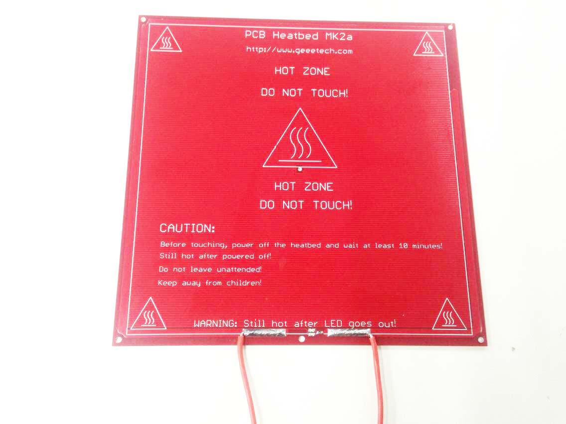
9 Attach he heated bed.
|
Required number |
Required parts |
|
1 |
MK2A Heat bed |
|
1 |
Borosilicate glass |
|
2 |
Heating wire |
|
1 |
Thermistor |
|
2 |
Thermometry wire |
|
4 |
Wing nut |
|
4 |
Spring |
|
4 |
M3 x35 screw |
|
4 |
clamp |
*All our heated bed is pre-soldered before shipping; you can attach the bed directly here. The following steps are just for reference if you need to change the bed in the future.
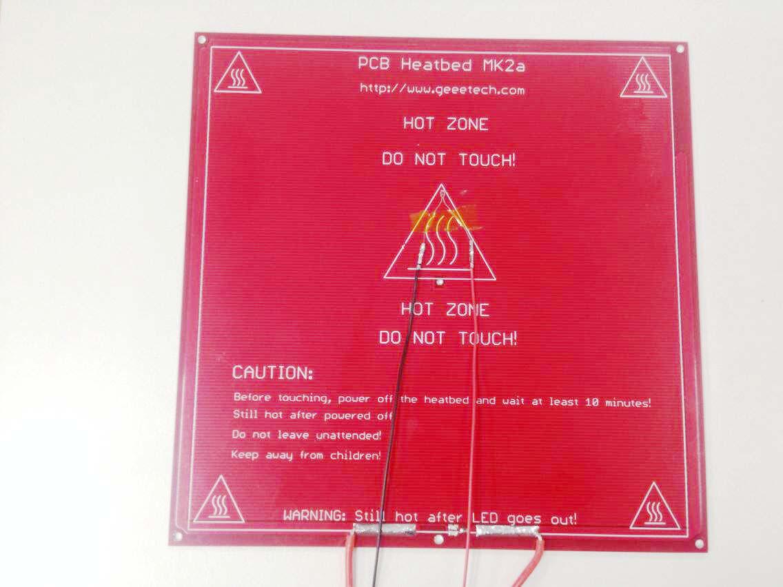
Step1. Solder the heating wire on the edge of the bed.
Step2. Take out the 2-pin DuPont wire and take off one the adapter.
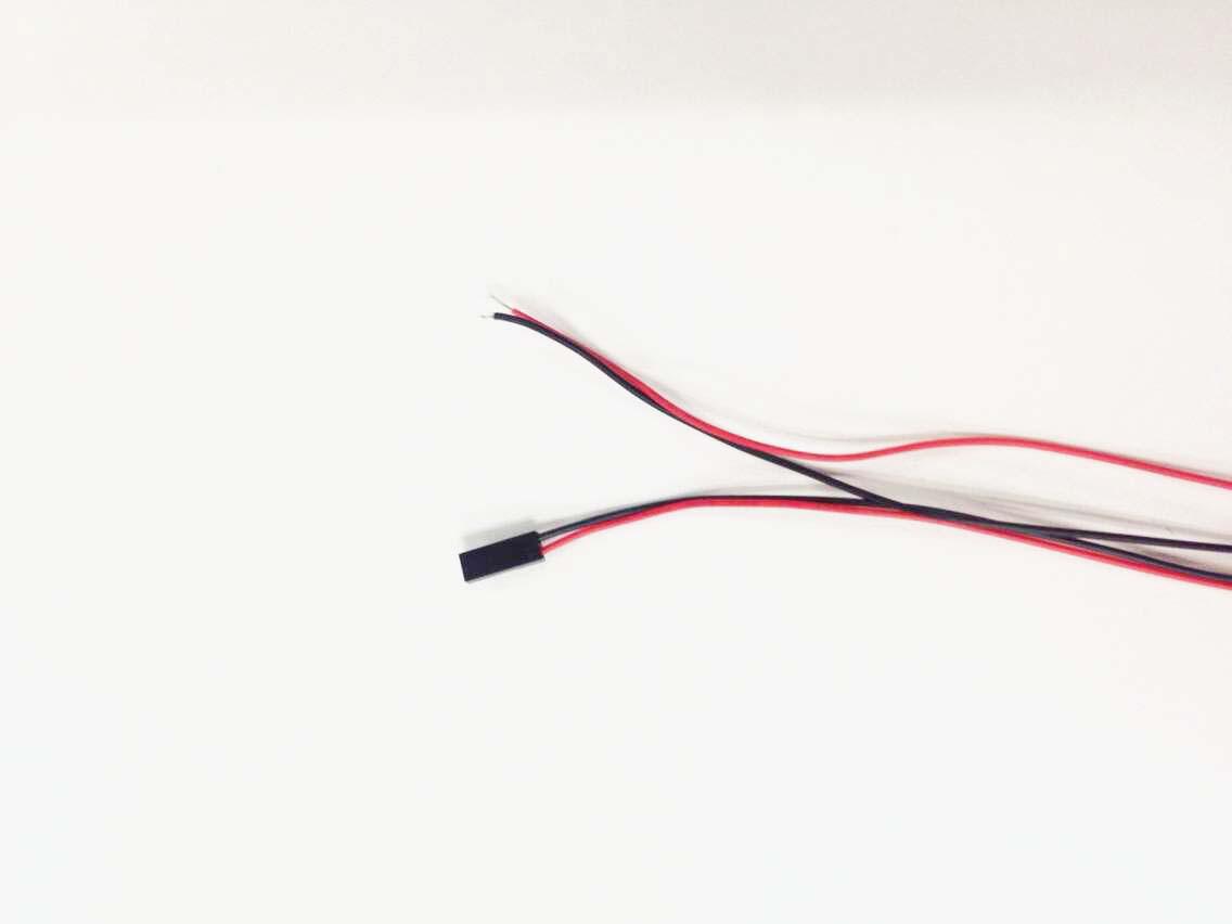
Step3. Solder the DuPont wire and the thermistor together.
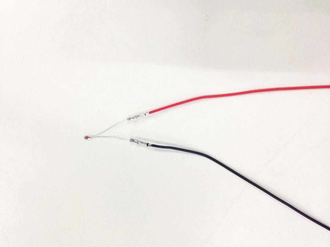
Step4. Attach the DuPont wire and the thermistor on the bed with Kapton tape.
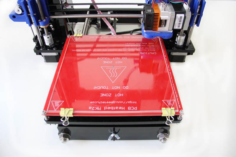
Step5. Mount the heat bed on the platform with 4 M3 x35 screws and wing nuts with springs in between. Clamp the heat bed and the glass sheet.
*the soldered side is better to be attached downwards.
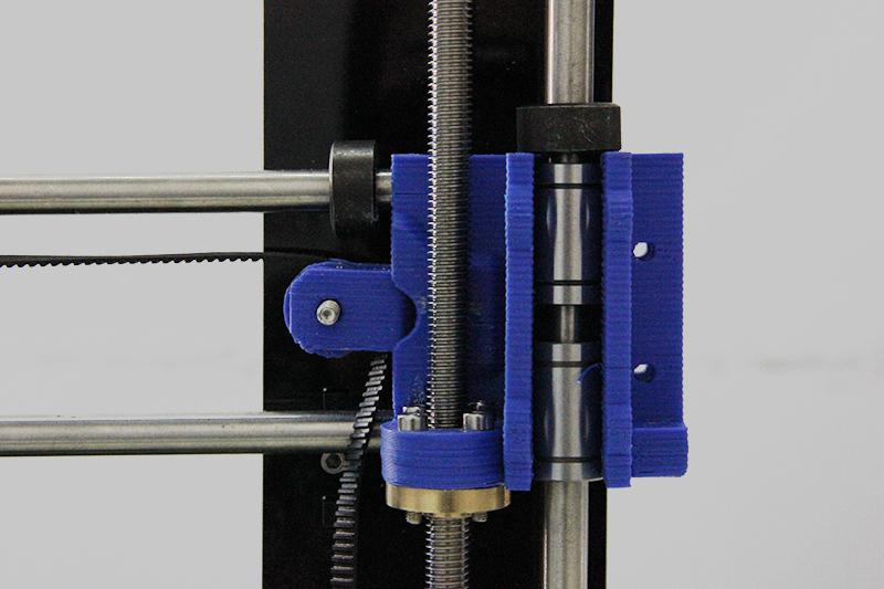
10 Mount the end stops.
Step 1.End stop of X-axis
|
Required number |
Required parts |
|
1 |
End stop |
|
2 |
M2.5 X 12 screw |
 2
2
Step2. End stop of Y-axis
|
Required number |
Required parts |
|
1 |
End stop |
|
2 |
M2.5 X 16 screw |
|
2 |
M2.5 Hex nut |
Note: there is no “+” and “-” for endstops, so there is no difference for the wires.
Step3. End stop of Z-axis
|
Required number |
Required parts |
|
1 |
End stop |
|
2 |
M 3 X 16 screw |
|
2 |
M 3 nut |
Here, you may need to use a bit force to drill the screw into the endstop.
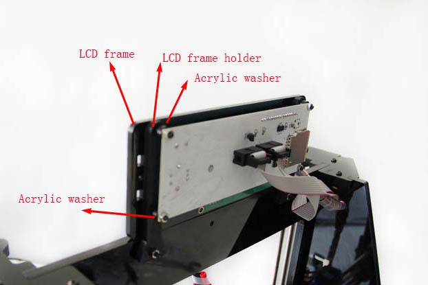
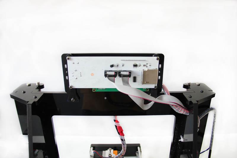
11 Mount the LCD panel frame.
|
Required number |
Required parts |
|
1 |
LCD 2004 |
|
1 |
LCD frame |
|
2 |
LCD frame holder |
|
4 |
Acrylic washer |
|
6 |
M3 x 20 screw |
|
4 |
M3 nut |
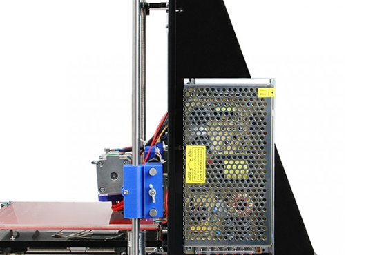
12 Mount the PSU
|
Required number |
Required parts |
|
1 |
Power supply |
|
3 |
M3 x 10 screw |
|
2 |
M3 x 16 bolt |
|
2 |
M3 nut |
|
1 |
3D Power cable |
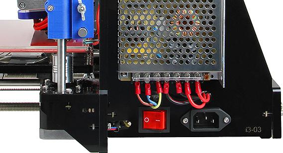
Step1. Mount the PSU (Power supply unit) on the right side panel with 3 M3 x 10 screws.
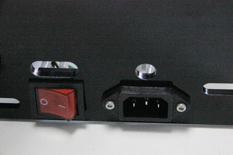
Step2. Mount the AC socket with M3 x 16 screws.
First you have to take off one end of the connectors to get both the power button and the power socket into the hole.
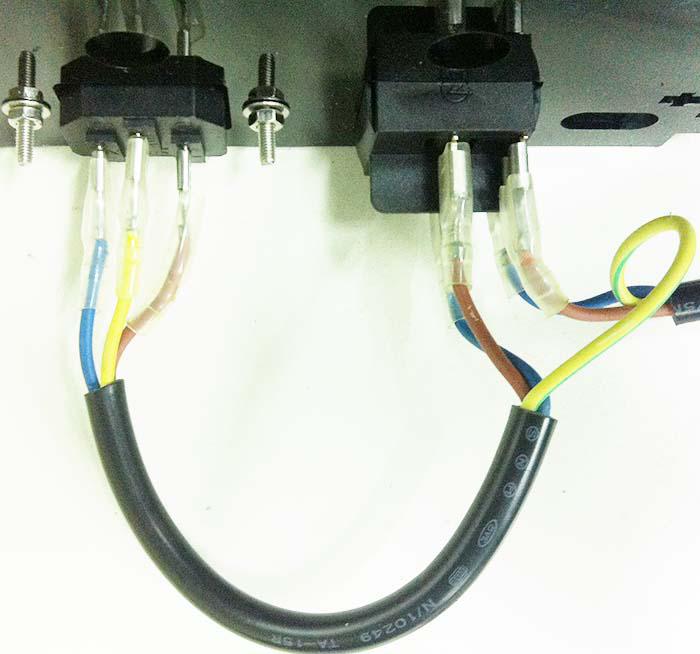
*(The connection of wire in this picture is very important; you should pay close attention in case the PSU suffer a shortcut)
Step3. Connect the power cable to PSU.
1) Mind the color of the wires. The wrong connection of the wire will cause serious damage to the PSU and even to the control board of the printer.
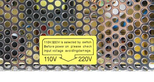
2) Pay attention to the switch on the right side of the PSU, there are two options of voltage: 110 V and 220V, choose according the standard in your country. As shown in the following picture. You can use some hard sticks to reach the switch.
see the finished picture here.
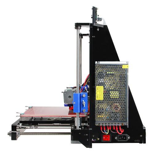
So far, we have finished all machine part, that’s all for today, tomorrow, we will continue with the building electric of the Prusa i3. Stay tuned!
for more detailed introduction of Geeetech prusa I3, please refer to geeetech online store.