Prusa I3 X
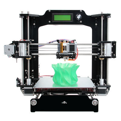
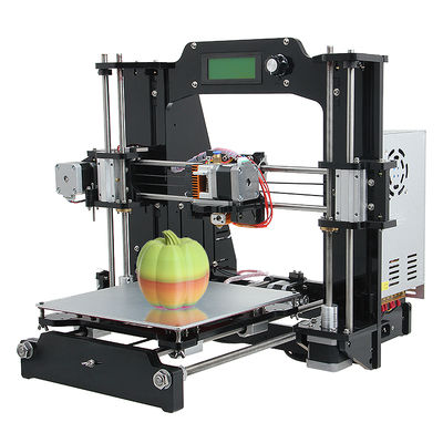
Geeetech Prusa I3 X is a new member of the prestigious Prusa I3 family, it was engineered to provide redefined usability, quality, performance and most important, best affordability in desktop 3D printer market. The Geeetech Prusa I3 X is made from piano-black laser-cut acrylic frame. To maintain the garage-built feel and the handmade charm, Geeetech Prusa I3 X is also a DIY kit, which provide you an unforgettable step-by-step learning experience of 3D printer from scratch. Geeetech Prusa I3 X has a wide range of customers , young or old, professional or amateur, as long as you have a passion for creativity, you can not afford to miss our Prusa I3 X.
Contents
Features
- Multiple 3D printing filament supportable: PLA,ABS, Wood-Polymer, Nylon, flexible PLA and PVA.
- 200x200x170mm printing volume, just right for you.
- 0.05mm printing precision.
- 8-mm-thick laser cut acrylic frame for rigidity and long life.
- Stainless steel rail rods, gears, bearings and connectors for smoother movement.
- All metal pulleys for improved functionality and performance.
- Super-flat aluminum alloy print surface for better adherence.
- Quick-release feed gears for faster and fluent filament feeding.
- filament size: 1.75mm.
- nozzles size: 0.30mm, 0.35mm.
Specification
Printing specifications:
Print technology: Fused Filament Fabrication (FFF).
Build volume: 200 x200x140mm
Printing Precision: 0.1-0.3mm
Filament diameter: 1.75mm
Nozzle diameter: 0.3mm, 0.35mm
Filament type: PLA,ABS, Wood-Polymer, Nylon, flexible PLA and PVA.
Software:
Operating system: Windows/Mac/Linux
Control software: Repetier-Host, Printrun
File format: .STL, G-code
Temperature:
Max heated bed temperature: about 110
Max extruder temperature: about 260°C
Electrical:
Power supply:
Input: 115V or 230V
Output:DC12V/0-15A
Connectivity: USB, SD card (support off-line printing)
Mechanical:
Frame: Laser-cut Acrylic plate of 8 mm thickness
Build Platform: Super-flat aluminum alloy+MK2A heat-bed
XYZ Rods: Wear-resistant, stainless steel
Stepper Motors: 1.8°step angle with 1/16 micro-stepping
Physical Dimensions & Weight:
Dimensions: 490 x 450 x 490 mm
Shipping box: 520 x 420 x 230 mm
Net weight: 8.7kg
Shipping weight: 10kg
Assembly
For detailed assembly instruction, please download here, or you can subscribe our Youtube for detailed videos.
Install the drivers and software
Install the drivers
Installing Drivers Before printing, you’ll need to install drivers. The kind of driver that a Prusa I3 requires in order to operate properly is called a USB Serial Driver. A USB Serial Driver is software that establishes a COM port.
Plug the USB into a USB port on your computer. Windows Update should automatically find and install the drivers. You’re done with installing the drivers!
Windows 8
When you attempt to install the unsigned 3rd party driver on Windows 8, you will most likely not be able to install because the file is not digitally signed. To get around this restriction, you must temporarily remove this restriction by following the instructions here .
Once you have followed the directions to disable driver signature enforcement, download the driver and click to install. This is only a temporary change, however, and restarting your computer after you have installed the driver will return your computer to its normal state.
Note that this involves restarting your computer, so make sure to close out all other windows. You may want to print out these instructions so you can refer to them while your computer is restarting.
Windows Manual Install
Note: In some cases the drivers will not install on their own. The drivers for Windows can be found in the following link:
drivers for GT2560 and Sanguinololu
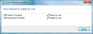
If the driver was not automatically installed, you may see this screen:
In this case, a. Click “Change Settings…” b. Select “Install driver software from Windows Update”. c. Click “Save Changes”. The FTDI drivers should now install successfully.
Attention: For those having difficulty selecting your COM port
If you have installed the USB serial driver successfully and you are still not able to connenct to your printer in Repetier Host, then windows has not recognized the newly installed driver. In Repetier Host, you may even notice an error message that is similar to this one:
Serial com error:System.IO.Ports.SerialErrorReceivedEventArgs
In some situations, a computer running windows will not automatically recognize a newly installed Serial driver. This means that you will have to update your newly installed driver manually.
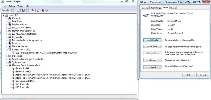
To manually update the driver, you will first need to plug the USB cable into your printer and attache the other end directly to one of your computer’s USB ports. Now, enter the ‘Device Manager’ in Windows and navigate to the hardware category called Ports (COM & LPT) and then left click on it once. You should notice the Ports category expand to reveal a Sub-Category called USB Serial (Communication Class, Abstract Control Model) (COM X); where X is the COM port number. You should be looking for that COM port number in Repetier Host after this procedure is completed; which can be found in “Printer Settings.”
You will need to right click on the USB Serial Sub-class and select proprties. In the drivers tab you will find a selection to update drivers, click on Update Drivers to access the next menu.
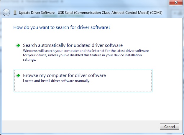
Now that you have selected which driver to update, you will have to tell Windows where the “updated” driver can be found. You should be presented with two options. Select “Browse my computer for driver software” to locate and install the driver software manually.
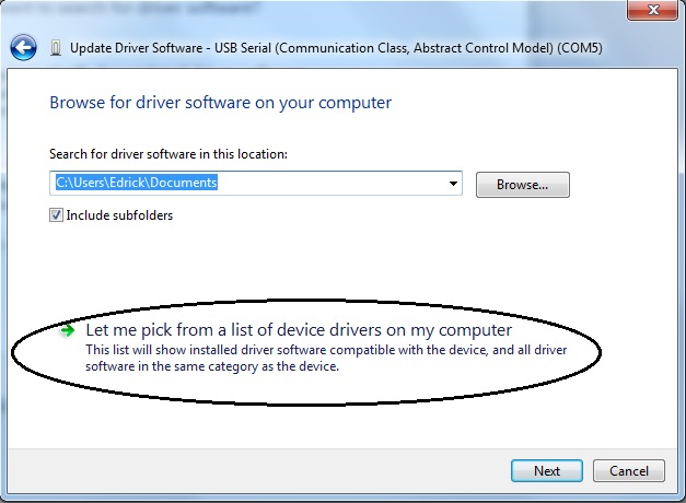
Next, you will be greeted by a menu that allows you to “Browse for driver software on your computer” You will be presented with two choices, select “Let me pick from a list of device drivers on my computer.” Now select the Serial port device and proceed with the installation.
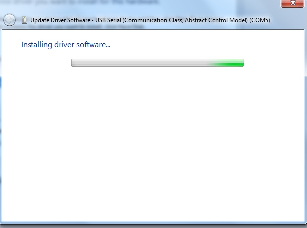
That is pretty much all there is to it. You will then see an installation indicator bar.
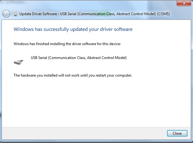
Once the installation is complete you will be notified that “Windows has successfully updated your driver software.” You will be prompted to restart your computer; you should do so.
Macbook (OS X) Manual Install
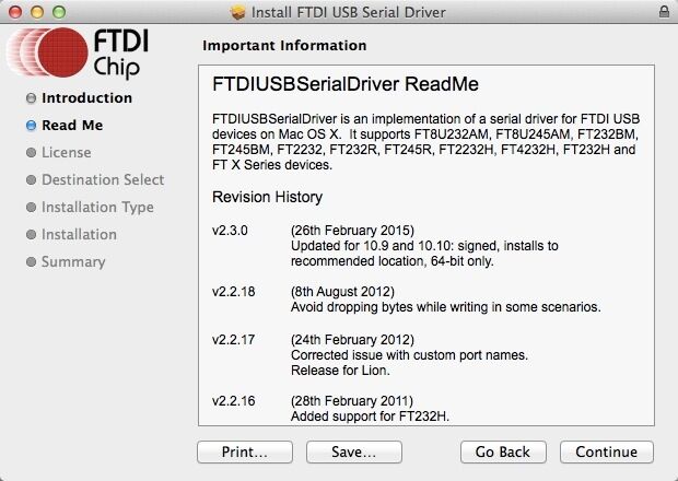
Download link of driver: http://www.ftdichip.com/Drivers/VCP.htm
Download the driver that is compatible with system version.
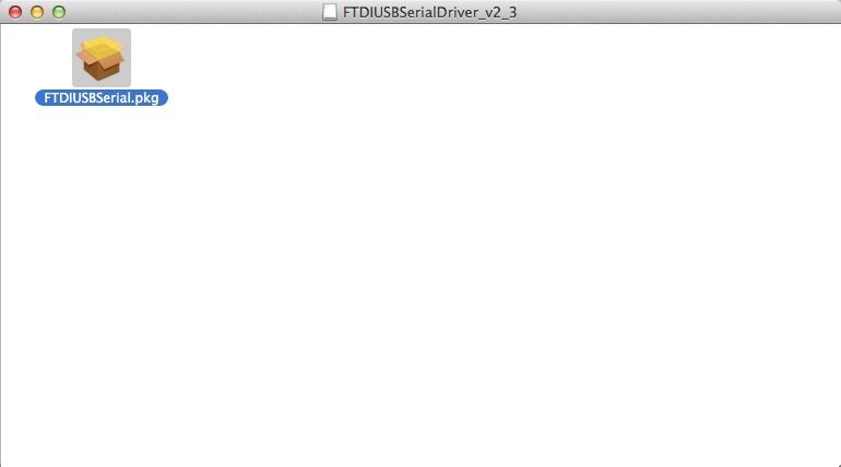
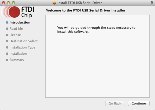
Open the downloaded file, you will see a .pkg file, Open "FTDIUSBSerial.pkg"
Click "Continue" in Instruction.
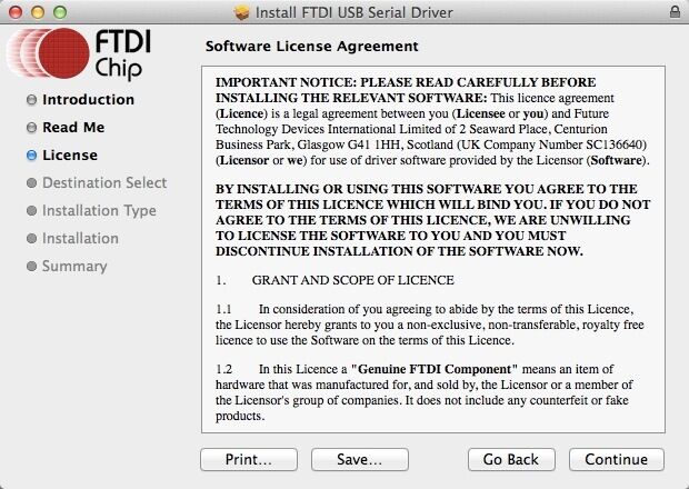
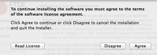
Click "Agree" to continue installation.
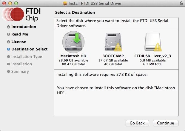
Select the installing destination and click "Continue".
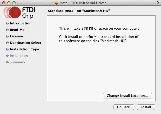
Click "Install" in Installatin Type.
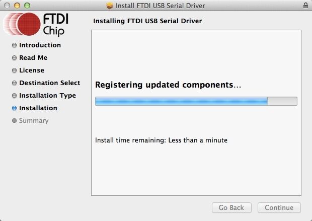
Mac will start to install the driver:

Once your computer restarts, try selecting the appropriate COM port and baud rate in Repetier Host and then connect.
Install Software
we will take windows OS as an example.
To install all required software by Prusa I3, please follow the steps provided below.
1) Download and install: RepetierGEtechSetup.exe
step 1,start the installer,choose the display language. step 2,click next to continue
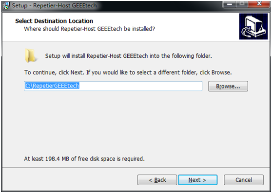
step3,select the destination where you would like to install the RepetierGEtechSetup.
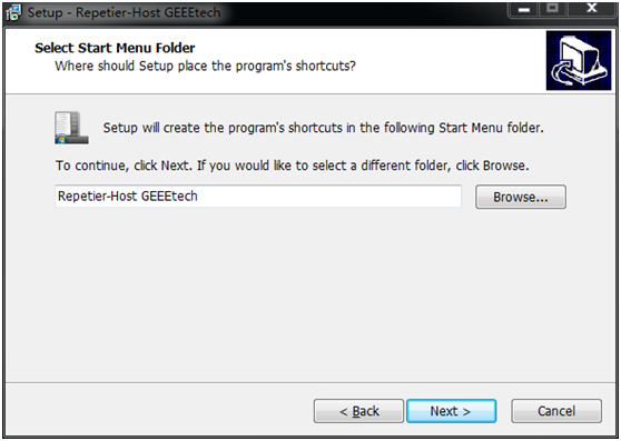
step4,select start menu folder and create a shortcut, click next to continue.
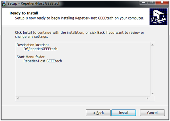
step 5,get ready to install. Click install.
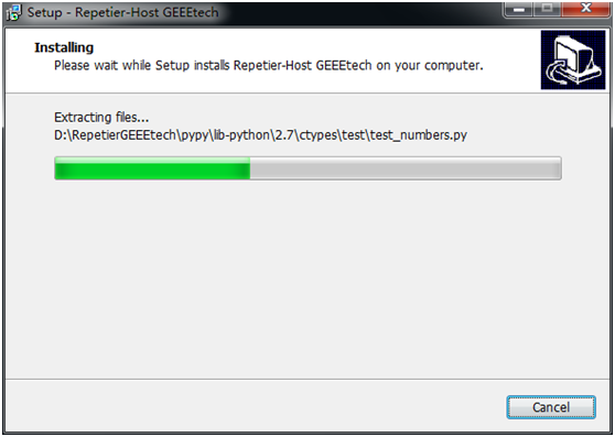
step 6,wait about half a minute while installing. The green bar will show you the rate.
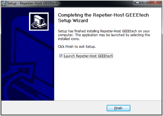
step 7,set up has finished the installing, you can choose to launch it immediately or exit out.
2) Plug the power cord into a wall outlet and the USB cable into a USB port on your computer. Windows should detect your motherboard and assign the appropriate driver.
3) Open Repetier Host and Connect to your Prusa I3!
Click on the Manual Controls Tab and click in a direction X or Y to test your connection. If you are having difficulty connecting, please review the following supportive documentation: Installing Drivers and How to connect.
Please note that if you have difficulty connecting, there might have been an issue with the installation process. Ensure that the following have been installed:
Download and install the Serial Driver.
Download and install Microsoft .netFrameWork 3.5
In Mac, you can download Repetier for Mac" at:
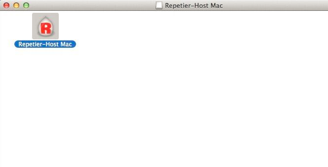
After downloading, open "Repetier-Host-Mac_56.dmg",then you will see the icon of "Repetier Host", open it.
How To set up
1. Plug the USB into your Prusa I3 and the other end into your computer.
Do not be alarmed if the standard messages do not appear. Because of the Prusa I3’s drivers, it may show up as a generic USB device.
2. Power on the Prusa I3. You can see the LED lights and fan come to life! You may be able to hear the motors idling.
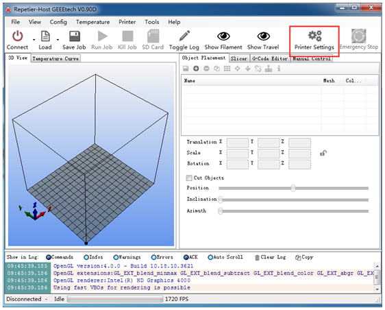
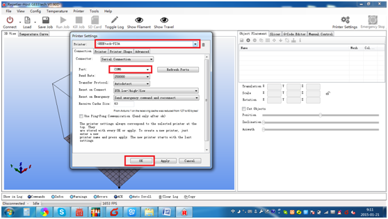
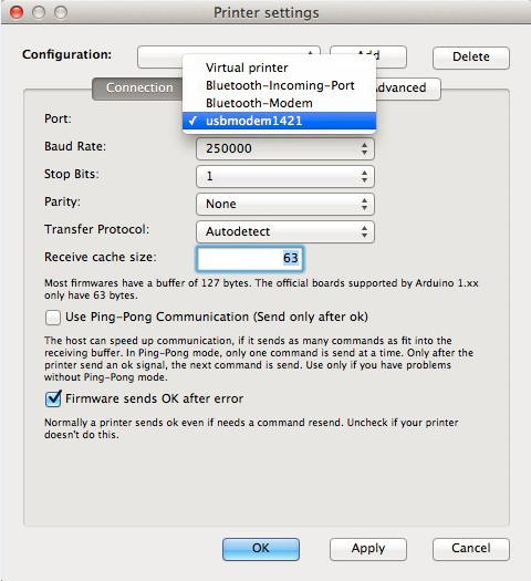
3. Open Repetier Host and ensure that you have a valid port selected for communications. To do this simply, click “Printer Settings” in the upper right-hand corner to bring up the printer settings menu.
4. Select the corresponding COM port, click OK to continue.
If you can not fond the COM port, click “refresh ports” and see if it appears. (It is usually the last one; you can check the device manager to see which port it is). PS: if you still cannot find the port, please reinstall your USB driver.
In Mac, you should finish step 5 in "Printer>Printer settings", step 4 is unnecessary
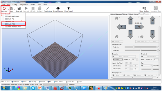
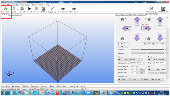
5. Hit "connect" in the upper left-hand corner, select GEEEtech PI3A. You should see the details of the connection in the console window in the bottom section of the screen. if your pronter is other models, you can select it, if you are not sure, you can skip it and connect directly.
If it turned green, it is connected.
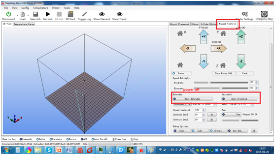
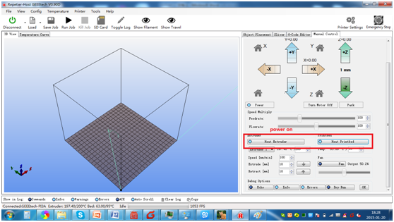
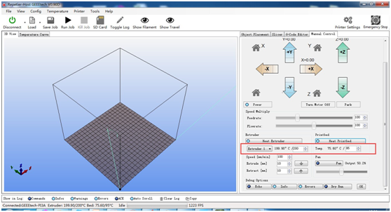
6. On the right panel, click the "Manual Control" tab. Scroll down and click both heat extruder and heat print bed buttons to activate your heaters. You will know they are on if they turn a bright blue.
The heat will gradually rise, as you will see from the status bar on the bottom of the window. The extruder should be set to 195° and the bed should be set to 95°.
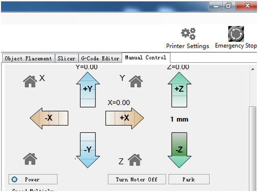
7. At the same time, you can click the arrows on the above panel to move the motors to check if they work well.
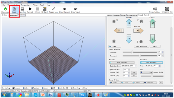
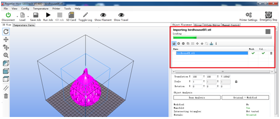
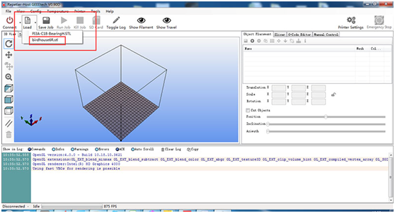
8. Click “load” to load the STL. File you need to print.
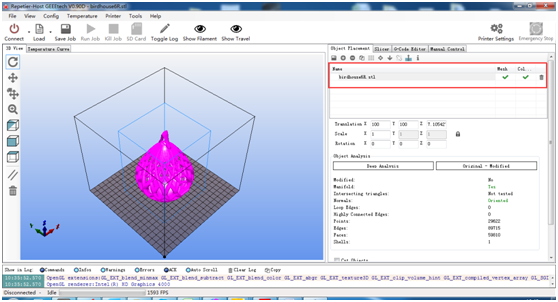
You can see now the model in the cubic box and on the right of the panel, you can see the loading bar.
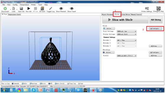
9. After loading, choose “slicer” > “configure” to set the printing configurations. You may need to wait for a minute.
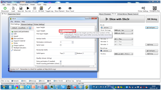
10x. First, you need to set the layers and perimeters. As you can see in the following picture, all you need to set is the layer height and the first layer height. Leave the rest as default. (For each setting, you can get a prompt to refer)
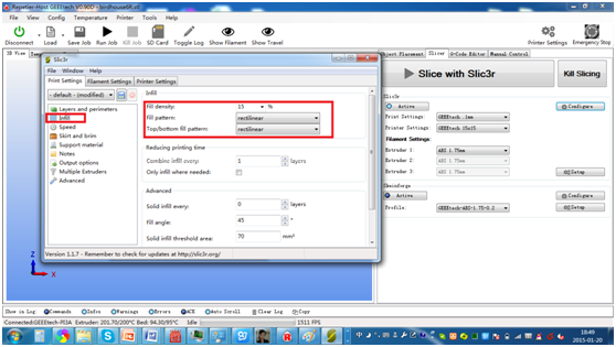
11. Set the printing infill density and pattern. Refer to the prompt.
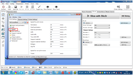
12. Set the printing speed. Again, refer to the prompt.
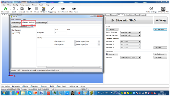
13. Filament setting. You just need to fill in the correct filament diameter.
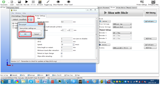
14. After setting, do not forget to save the settings and name each setting.
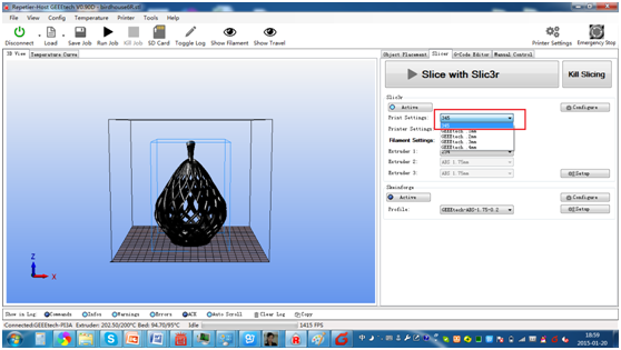
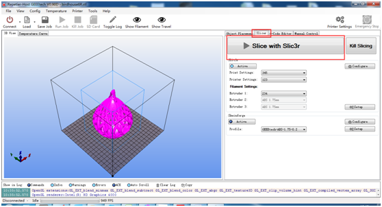
15. Select the settings you save on the right panel. Then click the “Slice with slice3r”to generate G- code. You may have to wait for a while.
16. click slicer button and slice with Slic3r.
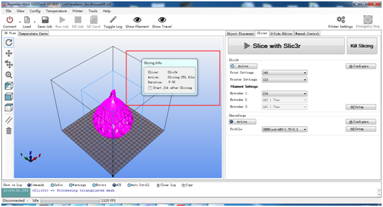
You can see the small window on the screen, the duration for the generation of G-code depends on the size of your file. It may take 1-2 minutes.
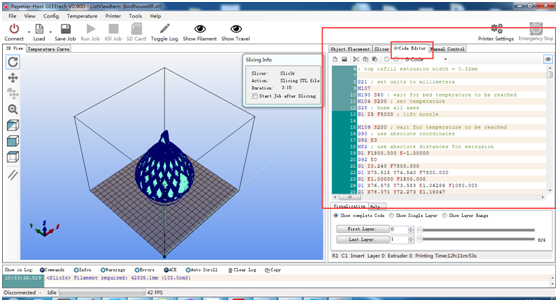
After that, you can see the code in G-code editor. There are two parameters deserves your attention. One is the bed temperature, another is the extruder temperature.
- Here is a temp reference.
 Filament Type	Bed temp	Extruder temp
 PLA	        50-100	        190-210
 ABS	        70-110	         220-240
if you are not familiar with Slic3r, you can read this Manual to start.
Leveling The Print Bed
Getting the bed level in relation to the X and Y axis is very important for getting prints to stick well and is one of the first steps you should do when receiving your printer . The first layer might have the right amount of squish in one area, but if another part of the bed is too low, that part of the print is more likely to come unstuck and begin to warp. The level is adjusted with the spring loaded screws, two at the front and one at the back. If you are using the standard kapton tape on the build platform and not a sheet of glass, you will need to poke holes in the tape in order to turn the leveling screws or print some thumbscrews and use a little super glue to screw them onto the bottom of the leveling screws. We suggest using the thumbscrew route so that you do not have to damage your kapton tape.
Leveling the bed with a piece of paper
You can check the level of the heated platform by using a piece of paper to check the gap under the nozzle. It’s best to do this with the platform heated to account for any change due to expansion.
Put the paper under the nozzle near one of the front screws and raise the bed .1mm at a time using the manual controls in the software interface while sliding the paper back and forth. Stop when you feel the nozzle start to grab a little bit.
Move the nozzle to the other front screw and adjust the screw until you get the same amount of friction as you felt with the first one. Then adjust the back screw the same way. Once you have adjusted each of the three screws, go back and check each one again, since adjusting one screw can affect another. You shouldn’t need to go around the bed more than twice.
Leveling the bed with a dial indicator
The best way to level the bed is with a dial indicator. This uses a spring loaded plunger to detect changes in distance. You can mount one the the front of the extruder, and zero the reading at one corner of the bed. The watch for the readout to change as you move it around the bed and adjust the screws accordingly. If the fit is too loose for the tab on your gauge, you can use a few pieces of tape to thicken it up.
Belt Tensioning
There are 3 belts to be adjusted on your Prusa I3. These steps will guide you through adjusted them.
Tools:
2.5 mm hex driver
1.5 mm hex driver
Steps
1. As always, before trying to work on any part of your Prusa I3, make sure that both the bed and extruder are turned off to prevent burns. Lowering the bed will also keep it out of the way so that you can access all the necessary parts more easily.
2. To test the belts, you need to be able to move the belts. This requires the motors to be turned off. Go to the Manual Control tab in Repetier Host and click the stop motors button. You should now be able to move the extruder around without much resistance.
3. Pull the extruder forward and out of your way.
4. Using the 2.5 mm hex driver, loosen the four 4 screws on the left side of your printer. This will allow the Y motor to move up and down. Note that you do not need to completely remove these screws as there is no need to remove this motor from the printer.
5. Using your hand, lift the Y motor enough to take the short loop of belt off the pulley attached to the motor. This belt is the source of most trouble with printing circles. If this is the only belt you wish to adjust, you can skip to step 11.
6. Loosen the screws on the inside of the pulleys on the left and right end of the back horizontal rod using your 1.5 mm hex driver. Make sure the back horizontal rod is centered by feeling the bearings that hold it on either side of the printer. You want to make sure it is even.
7. Push the extruder back and forwards. This movement should naturally align the belts, so that the back rod should not be moving side to side.
8. Once the belts are aligned, you can tighten the pulleys again with the 1.5 mm hex driver. The screws should be tight enough to hold on to the rod, but be careful not to strip the screws.
9. Put the short loop of belt back on the Y motor pulley by again lifting the motor up.
10. Make sure the two pulleys that the short loop of belt is on are aligned. If they are not, you can loosen the screw on the pulley on the back rod and carefully nudge it into place. Once it is aligned with the pulley on the y motor, tighten the screw.
11. Push the Y motor down firmly to draw the belt taut, and tighten the screws on the left side of the printer one-by-one to hold the motor in place.
12. Check that you can move the extruder back and forth. It may be a little resistant.
13. Slide the extruder forward so you can check the tension of the bottom belts behind the y carriages. These belts should be not too tight but not too loose. The most important thing is that they are of roughly equal tension.
14. You can tighten or loosen the bottom belts by adjusting the screw on the back of the y carriages with a 2.5 mm hex driver.
15. Now slide the extruder back to check the tension of the bottom belts in front of the y carriages. Again, these belts should be not too tight and not too loose. Using a 2.5 mm hex driver on the screws on the front of the y carriages, adjust the belts so that they are of roughly equal tension. 16. If the belts are still not moving smoothly, there may be a problem with the pulley alignment on the back horizontal rod. Using your 1.5 mm hex driver, loosen the screw on the pulleys so that you can move them into alignment, then tighten to hold them in place. This step can take some trial and error until you get everything properly aligned.
How to control on LCD
1.How to print from LCD
Note:
- 1)If you do not set the temperature of extruder and hot bed in g-code, you should manually heat up extruder and hotbed to proper temperature before printing.
- 2)If you do not set letting all the axes auto home in g-code, you should manually let all the axes auto home first.
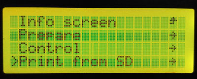
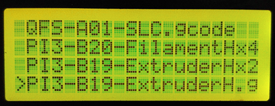
- Press the button>"Print from SD">Choose the file you want to print and press button.
2.How to let all the axes auto home
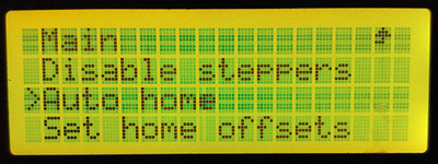
- Press button on LCD> “Prepare”>“Auto home”
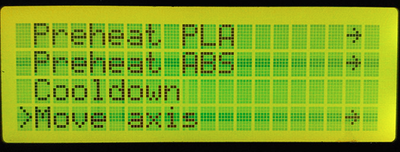
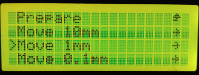
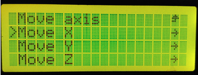
3.How to move the axis and extruder motor separately
- Press the button>”Prepare”>”Move axis”>”Move 10mm/1mm/0.1mm”>”Move X/Y/Z/extruder”>Rotate the button> Press button
Note: The extruder motor can not move unless the temperature is more than 180 degrees.
4.What if you can not move the axis with you hand
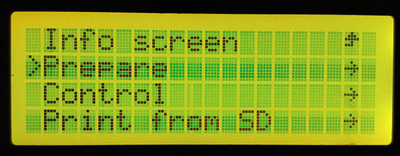
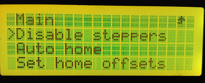
Press the button>“Prepare”>”Disable steppers”

5.How to set the temperature of extruder
Press the button>“Control”>”Temperature”>”Nozzle”>Rotate the button>Press the button
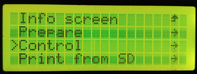

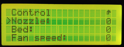
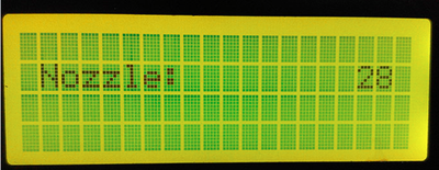
6.How to set the temperature of hot bed
“Control”>”Temperature”>”Bed”>Rotate the button


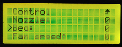
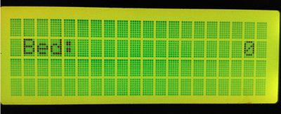
How to print off-line with GEEETECH I3
After leveling, you can print now, with an SD card, you are allowed to do off-line printing, here is a step by step instruction on how to set up for off-line printing:
Tip: It is recommended to use an SD card with the memory size less than 1G.
1.Open the software, and load the STL file to the slicer software, as shown below:
2. Click “Slice with Slic3r” under “Slicer” tab, as shown below:
3. The time for generating code depends on the size of model:
4. After generating the code of G-code, it will automatically skip to “G-code editor”, as shown the figure below:
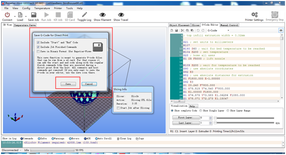
5. Click “save job” to save G-code file into your SD card (Note: Do not put it into any folder)
6 Plug the SD card into the slot on the back of the LCD panel.
7 turn on your printer; wait for about 30 seconds you can hear the LCD panel light up and the fan and motors are activated.
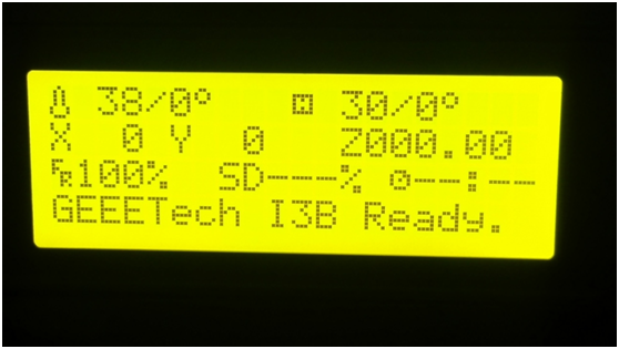
8. After about 30 seconds, you can see the “Geeetech I3B is ready” on the LCD panel.
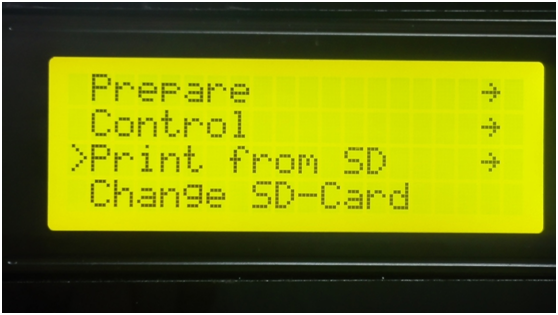
9. Now you can choose “ print from SD card”
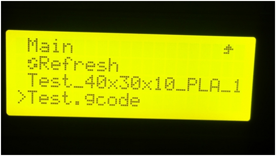
10. Choose the G-code file you have saved in the card.
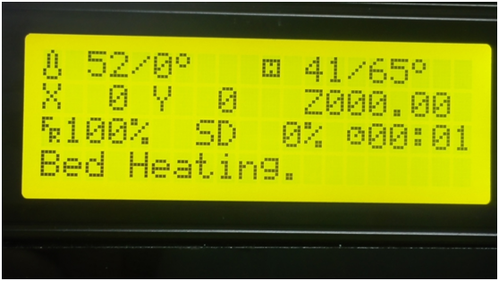
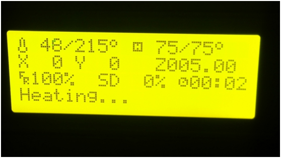
11, now you can see the heatbed is heating, the temperature is rising very quickly.
After the heatbed is heated to the rated temperature, the extruder will begin heating.
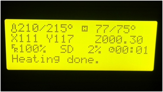
12. When you see “heating done”, the printer will begin printing immediately.
Slic3r Manual
This manual was written by Gary Hodgson.
Slic3r is a tool which translates digital 3D models into instructions that are understood by a 3D printer. It slices the model into horizontal layers and generates suitable paths to fill them.
Slic3r is already bundled with the many of the most well-known host software packages: Pronterface, Repetier-Host, ReplicatorG, and can be used as a standalone program.
This manual will provide guidance on how to install, configure and utilise Slic3r in order to produce excellent prints.
FAQs & SOLUTIONs
1.Fixing Extruder Jams and Flow Problems
