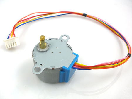
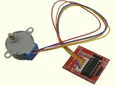
Stepper Motor 5V 4-Phase 5-Wire & ULN2003 Driver Board for Arduino
Contents
Stepper Introduction
A stepper motor is an electromechanical device which converts electrical pulses into discrete mechanical movements. The shaft or spindle of a stepper motor rotates in discrete step increments when electrical command pulses are applied to it in the proper sequence. The motors rotation has several direct relationships to these applied input pulses. The sequence of the applied pulses is directly related to the direction of motor shafts rotation. The speed of the motor shafts rotation is directly related to the frequency of the input pulses and the length of rotation is directly related to the number of input pulses applied.One of the most significant advantages of a stepper motor is its ability to be accurately controlled in an open loop system. Open loop control means no feedback information about position is needed. This type of control eliminates the need for expensive sensing and feedback devices such as optical encoders. Your position is known simply by keeping track of the input step pulses.
Features
- The rotation angle of the motor is proportional to the input pulse.
- The motor has full torque at standstill(if the windings are energized)
- Precise positioning and repeatability of movement since good stepper motors have an accuracy of – 5% of a step and this error is non cumulative from one step to the next.
- Excellent response to starting/stopping/reversing.
- Very reliable since there are no contact brushes in the motor. Therefore the life of the motor is simply dependant on the life of the bearing.
- The motors response to digital input pulses provides open-loop control, making the motor simpler and less costly to control.
- It is possible to achieve very low speed synchronous rotation with a load that is directly coupled to the shaft.
- A wide range of rotational speeds can be realized as the speed is proportional to the frequency of the input pulses.
Stepper motor 28BYJ-48 Parameters
- Model : 28BYJ-48
- Rated voltage : 5VDC
- Number of Phase : 4
- Speed Variation Ratio : 1/64
- Stride Angle : 5.625° /64
- Frequency : 100Hz
- DC resistance : 50Ω±7%(25℃)
- Idle In-traction Frequency : > 600Hz
- Idle Out-traction Frequency : > 1000Hz
- In-traction Torque >34.3mN.m(120Hz)
- Self-positioning Torque >34.3mN.m
- Friction torque : 600-1200 gf.cm
- Pull in torque : 300 gf.cm
- Insulated resistance >10MΩ(500V)
- Insulated electricity power :600VAC/1mA/1s
- Insulation grade :A
- Rise in Temperature <40K(120Hz)
- Noise <35dB(120Hz,No load,10cm)
Interfacing circuits
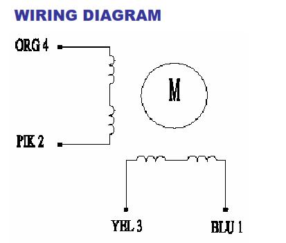
The bipolar stepper motor usually has four wires coming out of it. Unlike unipolar steppers, bipolar steppers have no common center connection. They have two independent sets of coils instead. You can distinguish them from unipolar steppers by measuring the resistance between the wires. You should find two pairs of wires with equal resistance. If you’ve got the leads of your meter connected to two wires that are not connected (i.e. not attached to the same coil), you should see infinite resistance (or no continuity).
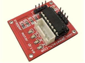
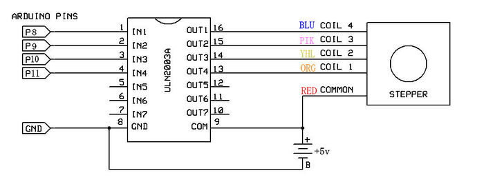
The simplest way of interfacing a unipolar stepper to Arduino is to use a breakout for ULN2003A transistor array chip. The ULN2003A contains seven darlington transistor drivers and is somewhat like having seven TIP120 transistors all in one package. The ULN2003A can pass up to 500 mA per channel and has an internal voltage drop of about 1V when on. It also contains internal clamp diodes to dissipate voltage spikes when driving inductive loads.To control the stepper, apply voltage to each of the coils in a specific sequence.
The sequence would go like this:
Here are schematics showing how to interface a unipolar stepper motor to four controller pins using a ULN2003A, and showing how to interface using four TIP120's.
Example code
Code
int Pin0 = 10;
int Pin1 = 11;
int Pin2 = 12;
int Pin3 = 13;
int _step = 0;
boolean dir = true;// gre
void setup()
{
 pinMode(Pin0, OUTPUT);
 pinMode(Pin1, OUTPUT);
 pinMode(Pin2, OUTPUT);
 pinMode(Pin3, OUTPUT);
}
 void loop()
{
 switch(_step){
   case 0:
     digitalWrite(Pin0, LOW);
     digitalWrite(Pin1, LOW);
     digitalWrite(Pin2, LOW);
     digitalWrite(Pin3, HIGH);
   break;
   case 1:
     digitalWrite(Pin0, LOW);
     digitalWrite(Pin1, LOW);
     digitalWrite(Pin2, HIGH);
     digitalWrite(Pin3, HIGH);
   break;
   case 2:
     digitalWrite(Pin0, LOW);
     digitalWrite(Pin1, LOW);
     digitalWrite(Pin2, HIGH);
     digitalWrite(Pin3, LOW);
   break;
   case 3:
     digitalWrite(Pin0, LOW);
     digitalWrite(Pin1, HIGH);
     digitalWrite(Pin2, HIGH);
     digitalWrite(Pin3, LOW);
   break;
   case 4:
     digitalWrite(Pin0, LOW);
     digitalWrite(Pin1, HIGH);
     digitalWrite(Pin2, LOW);
     digitalWrite(Pin3, LOW);
   break;
   case 5:
     digitalWrite(Pin0, HIGH);
     digitalWrite(Pin1, HIGH);
     digitalWrite(Pin2, LOW);
     digitalWrite(Pin3, LOW);
   break;
     case 6:
     digitalWrite(Pin0, HIGH);
     digitalWrite(Pin1, LOW);
     digitalWrite(Pin2, LOW);
     digitalWrite(Pin3, LOW);
   break;
   case 7:
     digitalWrite(Pin0, HIGH);
     digitalWrite(Pin1, LOW);
     digitalWrite(Pin2, LOW);
     digitalWrite(Pin3, HIGH);
   break;
   default:
     digitalWrite(Pin0, LOW);
     digitalWrite(Pin1, LOW);
     digitalWrite(Pin2, LOW);
     digitalWrite(Pin3, LOW);
   break;
 }
 if(dir){
   _step++;
 }else{
   _step--;
 }
 if(_step>7){
   _step=0;
 }
 if(_step<0){
   _step=7;
 }
 delay(1);
}
Stepper library
The Arduino programming environment comes with a function library for controlling a stepper motor. To use the library, in the Arduino Editor from the top menu bar: Sketch > Import Library > Stepper. Copy the example code below into an Arduino program.
Arduino Example Code Notes :
- The example code assumes that the stepper is being controlled by Arduino pins 8, 9, 10 and 11, but you can use any set of four pins.
- The "#define STEPS 100" line defines the number of steps per rev. A 3.75 deg motor has 96 steps/rev while a 7.2 deg motor has 48 steps/rev.
- The "Stepper stepper(STEPS, 8, 9, 10, 11)" line is where you enter the four pins used to control the stepper.
- The "stepper.setSpeed(x)" command sets the motor speed to x rpm.
- The "stepper.step(x)" command turns the motor x steps at the speed last set in the stepper.setSpeed() command. The motor turns one direction for postive x and the reverse direction for negative x.
Document
Reference Materials
- tigoe's blog http://www.tigoe.net/pcomp/code/circuits/motors/stepper-motors/
- silveir' blog http://silveiraneto.net/?s=stepper
- ME arduino course http://www.me.umn.edu/courses/me2011/arduino/technotes/stepper/index.html
How to buy
Click here to buy 5V 4-Phase 5-Wire Stepper Motor and Stepper Motor Driver Board ULN2003 for Arduino
