Difference between revisions of "Ramps1.4"
(→Source) |
|||
| (18 intermediate revisions by the same user not shown) | |||
| Line 1: | Line 1: | ||
| − | == | + | ==Introduction== |
| − | + | [[File:Ramps shoutu.jpg|500px|]] | |
| − | [[File: | ||
| − | ==Features== | + | Ramps is short for reprap Arduino mega pololu shield, it is mainly designed for the purpose of using pololu stepper driven board (similar to 4988 driven board). Ramps can only work when connected to its mother board Mega 2560 and 4988/DRV8825. |
| + | Owning to its stability in operation and great compatibility with most 3Dprinter (all reprap-model such as pursa i2 and i3). The combination of Ramps1.4+MEGA2560+A4988/DRV8825 is becoming a mainstream of DIY 3D printer control board. | ||
| + | ===Features=== | ||
| + | 1. Standard interfaces (as that of extruder) | ||
| − | + | 2. Reserved GCI like I2C and RS232 | |
| − | |||
| − | |||
| − | |||
| − | |||
| − | |||
| − | |||
| − | |||
| − | |||
| − | |||
| − | |||
| − | |||
| − | |||
| − | |||
| + | 3 MOSFET 3 MOSFET are applied to the heater/ fan and thermistor circuit. | ||
| − | + | 4. Adding another 5A to protect the component parts. | |
| − | + | 5. An 11A fuse is added to the hotbed | |
| − | + | 6. Support 5 stepper drive board | |
| − | + | 7. The adoption of Pin Header as pololu makes it more convenient to repair or change. | |
| − | + | 8. I2C and SPI are reserved for expanding | |
| − | + | 9. All the MOSFET can be controlled by PWM | |
| − | |||
| − | |||
| − | |||
| − | |||
| − | |||
| − | |||
| − | |||
| − | |||
| − | |||
| − | |||
| − | |||
| − | + | 10. Use the interface of servo motor to adjust the level of printing platform automatically. | |
| − | + | 11. Adding a SD module for SD ramps module. | |
| − | |||
| − | |||
| − | |||
| − | |||
| − | + | 12. LED can indicate the status of the heater (the open and close of MOS). | |
| − | |||
| − | |||
| − | |||
| − | |||
| − | |||
| − | |||
| − | |||
| − | |||
| − | |||
| − | |||
| − | |||
| − | |||
| − | |||
| − | |||
| − | |||
| − | |||
| − | |||
| − | |||
| − | |||
| − | |||
| − | |||
| − | |||
| − | |||
| − | |||
| − | |||
| − | + | 13. 2 stepper motor for Z axis in parallel. | |
| − | |||
| − | + | ===Overview and Hardware=== | |
| − | + | [[File:Rapms front.JPG|400px|]] [[File:Rampsback.jpg|400px|]] | |
| − | |||
| − | + | Weight: 68g | |
| + | Size: 102mm*60mm | ||
| − | |||
| − | |||
| − | |||
| − | |||
| − | === | + | ===Software=== |
| − | + | Compiling environment: Arduino IDE | |
| − | |||
| − | |||
| − | |||
| − | + | Firmware: Marlin | |
| − | |||
| − | |||
| − | + | PC software: Printrun, Repetier-Host | |
| − | |||
| − | |||
| − | + | ===Source=== | |
| − | [http:// | + | [http://www.geeetech.com/wiki/images/e/e1/Printrun-Win-Slic3r-10Mar2014.zip Printrun] |
| − | + | [http://www.geeetech.com/wiki/images/3/36/SetupRepetierHost_1_00.zip Repetier-Host] | |
| − | + | [http://www.geeetech.com/wiki/images/3/36/Arduino-1.0.5-r2-windows.zip Arduino IDE] | |
| − | + | [http://www.geeetech.com/wiki/images/4/4d/Arduino-1.5.6-r2-windows.zip Arduino IDE] | |
| − | + | [http://www.geeetech.com/wiki/images/3/39/Marlin-Marlin_v1.zip Marlin] | |
| − | |||
| − | + | [http://www.geeetech.com/wiki/images/c/cc/Arduino_1.0.1_for_Mac.zip Arduino 1.0.1 for Mac] | |
| − | === | + | ==Interface== |
| + | ===Interface Layout=== | ||
| − | + | [[File:线路图.jpg|700px|]] | |
| − | + | ===Interface specifications=== | |
| − | [[File: | + | [[File:Ramps interfaces.jpg]] |
| − | |||
| − | + | 2 power interfaces 12v 11a/12v 5a | |
| + | 6 motors (one for X axis, one for Y axis, 2 for Z axis, 2 for extruder | ||
| + | 2 interfaces for LCD&SD | ||
| + | 6 interfaces for end stop(X/Y/Z min, X/Y/Z max) | ||
| + | 3 interfaces for PWM (one for hotbed, one for fan and one for extruder) | ||
| + | 3 interfaces for thermistor | ||
| − | |||
| − | + | ===Jumper Instruction=== | |
| − | + | [[File:Ramps jumper.jpg]] | |
| − | + | Step size of stepper driver (A4988) | |
| − | + | jumper Yes/No stepsize | |
| + | ms1 ms2 ms3 | ||
| + | no no no fullstep | ||
| + | yes no no halfstep | ||
| + | no yes no 1/4step | ||
| + | yes yes no 1/8step | ||
| + | yes yes yes 1/16step | ||
| − | |||
| − | + | Step size of stepper driver (Drv8825) | |
| − | + | jumper Yes/No step size | |
| − | + | ms1 ms2 ms3 | |
| − | + | no no no full step | |
| − | + | yes no no half step | |
| − | + | no yes no 1/4 step | |
| − | + | yes yes no 1/4 step | |
| − | + | no no yes 1/16 step | |
| + | yes no yes 1/32 step | ||
| + | no yes yes 1/32step | ||
| + | yes yes yes 1/32step | ||
| − | == | + | ==Development Environment setting== |
| − | ==== | + | ===Interface Connecting and Setting=== |
| − | |||
| − | == | ||
| − | |||
| − | + | [[File:Ramps c setting.jpg|600px|]] | |
| − | + | Precautions: | |
| + | Like other electronics, the inverse connection of power supply can cause irreparable damage to the board (4988 included). You are advised to connect all the components before testing. | ||
| − | + | ===File Burning=== | |
| + | As Ramps1.4 is just the shield board of Mega2560, the firmware must be burned into Mega2560. | ||
| − | + | ===Software Setting=== | |
| + | 1.Before uploading, driver should be installed for windows. Then choose the type of board: Tools > Board > Arduino Mega 2560 or Mega ADK. (Picture below) | ||
| − | + | [[File:Bsecet.jpg|500px|]] | |
| − | |||
| − | |||
| − | + | 2.Select the serial port: Tools > Serial Port, the serial port for mega is usually the last one. | |
| − | + | [[File:Portselect.jpg|500px|]] | |
| − | |||
| − | |||
| − | |||
| − | |||
| − | |||
| − | |||
| − | |||
| − | |||
| − | + | 3.Click[[File:Button1.jpg]]to check if there is any mistake. If not, click[[File:Button2.jpg]]to upload. | |
| − | |||
| − | |||
| − | |||
| − | |||
| − | + | [[File:Rumba 11.jpg]] | |
| − | |||
| − | |||
| − | |||
| − | |||
| − | + | 4.During the process of uploading, the 3 LEDs corresponding to TX, RX and L on mega board will blink, if the blink stops, the uploading is done. | |
| − | |||
| − | |||
| − | + | [[File:Done uploading.jpg]] | |
| − | |||
| − | |||
| − | |||
| − | + | After the uploading, you can go on with the next step. If the uploading is unsuccessful, read the error report on IDE, figure out the problem, and then try again. some frequent errors are: a wrong select of board type and serial port. | |
| − | |||
| − | |||
| − | |||
| − | |||
| − | |||
| − | |||
| + | The connection of Repetier-Host | ||
| − | + | 1. Click configuration> printer setting | |
| − | + | ||
| − | + | [[File:Rh1.jpg|500px|]] | |
| − | + | ||
| − | + | 2. Set the communication port (the COM port for mega) and the Baud rate. Then click ok | |
| − | + | ||
| − | + | [[File:Rh2.jpg|500px|]] | |
| − | + | ||
| − | + | 3. Click “connect”> upload. Choose the GCODE file you are printing. | |
| − | + | ||
| − | + | [[File:Rh3.jpg|500px|]] | |
| − | + | ||
| − | + | ==Get Started== | |
| − | + | Mega 2560 is the CPU of a 3d printer, manipulating the whole process of printing. Mega 2560 can’t be put in use directly without uploading firmware. | |
| − | + | ||
| − | + | 1. Firmware uploading- marlin. | |
| − | + | ||
| − | + | 2. Setting parameters of the firmware | |
| − | + | ||
| − | + | 3. The parameters that need setting are as below, for those not mentioned just leave them as default. | |
| − | + | ||
| − | + | #define BAUDRATE 250000 | |
| − | + | ||
| − | + | This parameter is for the baud rate of serial port. Note: a successful communication can be realized only when the Baud rate of upper computer is identical with that of Firmware. The Baud rate is not set in random. The common Baud rate are: 2400,9600,19200,38400,57600,115200,250000. The last three are frequently used for 3D Printer. | |
| − | + | ||
| − | + | #define MOTHERBOARD 33 | |
| − | + | ||
| − | + | This parameter is set for board type. 3D Printer has many types of main board, and the setting of IOs is different, therefore, the parameter has to correspond to the type of your board, or it can’t operate normally. The parameter of mega should be 33(single- nozzle) or 34 (dual-nozzle). For other board, you can refer to the annotation on the board. | |
| − | + | ||
| − | + | #define TEMP_SENSOR_0 3 | |
| − | + | #define TEMP_SENSOR_BED 3 | |
| − | + | ||
| − | + | The two parameters are set for the type of temperature sensor respectively. They are the critical parameter to check if the sensor read temperature correctly. The printer can’t operate normally, even has potential risk (damage the device and even worse). You must modify depending on the temperature sensor you use. | |
| − | | | + | |
| − | | | + | #define EXTRUDE_MINTEMP 170 |
| − | + | ||
| − | + | This parameter is set to avoid the potential risks when the extruder operates before reaching the rated temperature. If you use other 3D Printer, such as printer to make Chocolates, 45℃ is appropriate, so that the parameter configured to a lower value(such as 40℃). | |
| − | + | ||
| − | + | const bool X_ENDSTOPS_INVERTING = true; | |
| − | + | const bool Y_ENDSTOPS_INVERTING = true; | |
| − | + | const bool Z_ENDSTOPS_INVERTING = true. | |
| − | |||
| − | |||
| − | |||
| − | |||
| − | |||
| − | |||
| − | |||
| − | |||
| − | |||
| − | |||
| − | |||
| − | |||
| − | |||
| − | |||
| − | |||
| − | |||
| − | |||
| − | |||
| − | |||
| − | |||
| − | |||
| − | |||
| − | |||
| − | |||
| − | | | ||
| − | | | ||
| − | |||
| − | |||
| − | |||
| − | |||
| − | |||
| − | |||
| − | |||
| − | |||
| − | |||
| − | |||
| − | |||
| − | |||
| − | |||
| − | |||
| − | |||
| − | |||
| − | |||
| − | |||
| − | |||
| − | |||
| − | |||
| − | |||
| − | |||
| − | |||
| − | |||
| − | |||
| − | |||
| − | |||
| − | |||
| − | |||
| − | |||
| − | |||
| − | |||
| − | | | ||
| − | |||
| − | |||
| − | | | ||
| − | |||
| − | |||
| − | |||
| − | |||
| − | |||
| − | |||
| − | |||
| − | |||
| − | |||
| − | |||
| − | |||
| − | |||
| − | |||
| − | |||
| − | |||
| − | |||
| − | |||
| − | |||
| − | |||
| − | |||
| − | |||
| − | |||
| − | |||
| − | |||
| − | |||
| − | |||
| − | |||
| − | |||
| − | |||
| − | |||
| − | |||
| − | |||
| − | |||
| − | |||
| − | |||
| − | |||
| − | |||
| − | |||
| − | |||
| − | |||
| − | |||
| − | |||
| − | |||
| − | |||
| − | |||
| − | |||
| − | |||
| − | |||
| − | |||
| − | |||
| − | |||
| − | |||
| − | |||
| − | |||
| − | |||
| − | |||
| − | |||
| − | |||
| − | |||
| − | |||
| − | |||
| − | |||
| − | |||
| − | |||
| − | |||
| − | |||
| − | |||
| − | |||
| − | |||
| − | |||
| − | |||
| − | |||
| − | |||
| − | |||
| − | |||
| − | |||
| − | |||
| − | |||
| − | |||
| − | |||
| − | |||
| − | |||
| − | |||
| − | |||
| − | |||
| − | |||
| − | |||
| − | |||
| − | |||
| − | |||
| − | |||
| − | |||
| − | |||
| − | |||
| − | |||
| − | |||
| − | |||
| − | |||
| − | |||
| − | |||
| − | |||
| − | |||
| − | |||
| − | |||
| − | |||
| − | |||
| − | |||
| − | |||
| − | |||
| − | |||
| − | |||
| − | |||
| − | |||
| − | |||
| − | |||
| − | |||
| − | |||
| − | + | The three parameters are set for the end stops of three axes. If the configuration is true, the end stop outputs 1 in default condition, and outputs 0 when triggered. That is to say, mechanical end stop should connect to the NO (normally open) contactor. If it is connected to the NC (normally closed), true should be changed to false. | |
| − | + | #define INVERT_X_DIR false | |
| + | #define INVERT_Y_DIR true | ||
| − | + | Mistakes are often made in the above two parameters. The parameters are different for different machinery. In principle, the origin should be at lower-left corner of the print platform (origin: [0, 0]), or at up-right corner (origin: [max, max]). Only in this way will the printing be correct, otherwise, the printing is the mirror image of one axis which is not what expected. | |
| − | In | ||
| − | + | #define X_HOME_DIR -1 | |
| + | #define Y_HOME_DIR -1 | ||
| + | #define Z_HOME_DIR -1 | ||
| − | + | If the position of the origin is the minimum, the parameter is -1; if it is the maximum, the parameter is 1. | |
| − | |||
| − | |||
| − | |||
| − | |||
| − | |||
| − | |||
| − | |||
| − | + | #define X_MAX_POS 205 | |
| + | #define X_MIN_POS 0 | ||
| + | #define Y_MAX_POS 205 | ||
| + | #define Y_MIN_POS 0 | ||
| + | #define Z_MAX_POS 200 | ||
| + | #define Z_MIN_POS 0 | ||
| − | + | These parameters are crucial to the printing size. Fill in parameters by reference to the coordinate graphs. It is important to note that the origin is not the printing center and the real printing center usually lies at [(x.max - x.min)/2, (y.max -y.min/2)]. The coordinate of central will be used in the slice tool. The printing center’s coordinate must correspond to the parameter configuration, or it will print to the outside of the platform. | |
| − | |||
| − | + | #define HOMING_FEEDRATE {50*60, 50*60, 4*60, 0} | |
| − | + | The parameter means the homing speeds (mm/min). This parameter can be set as default if you use the x-axis and y-axis adopt synchronous belt drive and z-axis adopts screw drive. | |
| − | |||
| − | + | #define DEFAULT_AXIS_STEPS_PER_UNIT {85.3333, 85.3333, 2560, 158.8308} | |
| − | + | These parameters are crucial to the printing size. These parameters indicate the pulse the axis need when operating 1mm. they are corresponding to x, y, z axis and extruder respectively. In most cases these figure should be calculated by yourself, you can refer to: http://calculator.josefprusa.cz/#steppers. | |
| − | [[File: | + | So far, the commonest parameters have been configured and the printer can work now. In addition, if the 2004 LCD needs verifying, you should delete the “//” from “//#define REPRAP_DISCOUNT_SMART_CONTROLLER” to ensure the normal working. |
| + | |||
| + | |||
| + | |||
| + | ==Extensible Applications== | ||
| + | |||
| + | Upload through Bluetooth | ||
| + | |||
| + | [[File:Ramps ea.jpg]] | ||
| + | The COM should be set as (9600, N, 8, 1) | ||
| + | The command for Bluetooth module: | ||
| + | |||
| + | AT OK | ||
| + | AT+BAUD8 OK115200BAUD (set baud rate for RAMPS/Arduino Mega) | ||
| + | AT+NAMEPRUSAI3 OKsetname (optional set name, default: linvor) | ||
| + | AT+PIN0000 OKsetPIN (optional set pin, default: 1234) | ||
| + | |||
| + | |||
| + | |||
| + | ==FAQS== | ||
| + | 1.How many extruders can ramps support? | ||
| + | |||
| + | Ramps 1.4 support 5 A4988 driving boards, which are for X/Y/Z/axis and 2 extruders respectively, so the ramps can support at most 2 extruders. | ||
| + | |||
| + | |||
| + | 2. What should I note when provide power for ramps? | ||
| + | |||
| + | The recommended power supply for Ramps is 12V, especially for Mega2560. If supplied over 12v, Mega will over heat, resulting in instability of operation, the serial port communication is was at times strong and at other times weak. Do make sure the power is 12v, if you don’t have switching power supply of 12v, please take down the diode D1 on Ramps if you use a greater power supply. | ||
| + | The current is decided by the use of hotbed. If you use a hotbed, an idea power supply is 12v 17A, 200W. If not, 5A is enough. | ||
| + | |||
| + | |||
| + | 3. Can fan be added to Ramps? | ||
| + | |||
| + | Yes. If you use only one extruder, you can connect the fan to the 2 pins in the middle of the 6 blue output pins. If you use two extruders, the fan cannot be connected to ramps directly; you should connect it to a power source that is controlled manually. Or you can build an external circuit, the pins of which should be set in the firmware, | ||
| + | |||
| + | |||
| + | 4. What is the difference between ramps and ultimaker? | ||
| + | |||
| + | In the respect of function, they are totally alike. But there are some difference, one lies in the configuration of I/O pins. Another lies in the way of reading temperature. Ultimaker uses thermocouple and temperature control board (AD597), ramps uses NTC thermistor 100K. If you want to use thermocouple and temperature control board for ramps, you should take down the pull-up resistor one the thermistor of hot end. | ||
| + | |||
| + | |||
| + | 5. Can Ramps replace ultimaker to make an ultimaker printer? | ||
| + | |||
| + | Yes, it can, but you need to pay attention to the points we’ve mentioned in chapter Ⅴ .The ultimaker printer is one kind of reprap, as well as standard three- axis rectangular coordinates | ||
| + | |||
| + | |||
| + | 6. The temperature displayed is not normal. | ||
| + | |||
| + | A. you may select the wrong thermistor in marlin, we often choose 1. | ||
| + | |||
| + | B. The thermistor is Brocken or there is short-circuit occurred in the 2 pins of the thermistor. | ||
| + | |||
| + | C. The electrolytic capacitor on ramps is broken. | ||
| + | |||
| + | |||
| + | 7. The motor jitters. | ||
| + | |||
| + | A. It is a matter of poor connection, | ||
| + | |||
| + | B. A4988 has broke down, | ||
| + | |||
| + | C, the VREF is not right. | ||
| + | |||
| + | |||
| + | 8. The scope of motor is too small. | ||
| + | |||
| + | You may forget putting the jumper cap, or the parameter you set is wrong. | ||
| + | |||
| + | |||
| + | 9. The program uploading is not successful. | ||
| + | |||
| + | The USB cable doesn’t work; the version of Arduino IDE you use is not compatible; the select of COM is wrong. | ||
| + | |||
| + | |||
| + | 10. The hotbed and extruder can’t heat. | ||
| + | |||
| + | A. The MOSFET is broken. | ||
| + | |||
| + | B. The thermistor is not connected. | ||
| + | |||
| + | |||
| + | 11 the motor of extruder doesn’t work. | ||
| + | |||
| + | The thermistor is not connected; the temperature is not enough; A4988 broke down; ramps 1.4 broke down. | ||
| + | |||
| + | |||
| + | ==where to get== | ||
| + | |||
| + | ckick here to get your ramps 1.4 | ||
| + | |||
| + | [http://www.geeetech.com/ramps-14-reprap-mega-pololu-a4988-extend-shield-p-606.html ramps1.4] | ||
| − | + | [http://www.geeetech.com/reprap-mega-pololu-shield-electronicsramps-pcb-kits-p-647.html ramps1.4 PCB kit] | |
| − | |||
Latest revision as of 06:49, 29 April 2015
Contents
Introduction
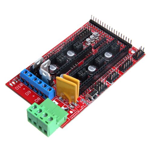
Ramps is short for reprap Arduino mega pololu shield, it is mainly designed for the purpose of using pololu stepper driven board (similar to 4988 driven board). Ramps can only work when connected to its mother board Mega 2560 and 4988/DRV8825. Owning to its stability in operation and great compatibility with most 3Dprinter (all reprap-model such as pursa i2 and i3). The combination of Ramps1.4+MEGA2560+A4988/DRV8825 is becoming a mainstream of DIY 3D printer control board.
Features
1. Standard interfaces (as that of extruder)
2. Reserved GCI like I2C and RS232
3 MOSFET 3 MOSFET are applied to the heater/ fan and thermistor circuit.
4. Adding another 5A to protect the component parts.
5. An 11A fuse is added to the hotbed
6. Support 5 stepper drive board
7. The adoption of Pin Header as pololu makes it more convenient to repair or change.
8. I2C and SPI are reserved for expanding
9. All the MOSFET can be controlled by PWM
10. Use the interface of servo motor to adjust the level of printing platform automatically.
11. Adding a SD module for SD ramps module.
12. LED can indicate the status of the heater (the open and close of MOS).
13. 2 stepper motor for Z axis in parallel.
Overview and Hardware
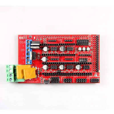
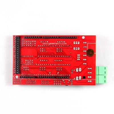
Weight: 68g Size: 102mm*60mm
Software
Compiling environment: Arduino IDE
Firmware: Marlin
PC software: Printrun, Repetier-Host
Source
Interface
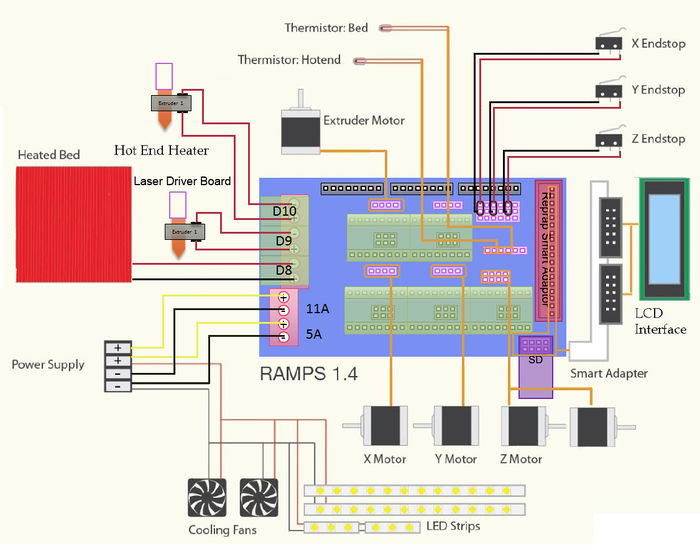
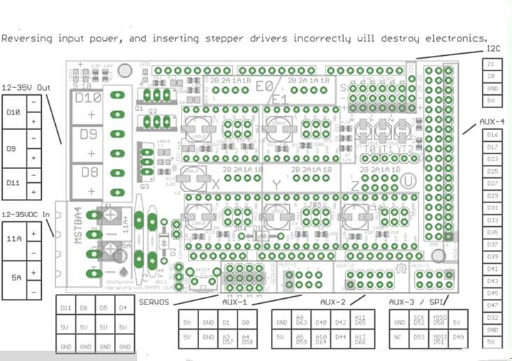
Interface Layout
Interface specifications
2 power interfaces 12v 11a/12v 5a
6 motors (one for X axis, one for Y axis, 2 for Z axis, 2 for extruder
2 interfaces for LCD&SD
6 interfaces for end stop(X/Y/Z min, X/Y/Z max)
3 interfaces for PWM (one for hotbed, one for fan and one for extruder)
3 interfaces for thermistor
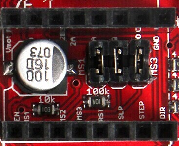
Jumper Instruction
Step size of stepper driver (A4988)
  jumper       Yes/No     stepsize
   ms1     ms2      ms3
   no      no       no     fullstep
   yes     no       no     halfstep
   no      yes      no     1/4step
   yes     yes      no     1/8step
   yes     yes      yes    1/16step
Step size of stepper driver (Drv8825)
  jumper   Yes/No       step size
   ms1     ms2      ms3
   no      no       no    full step
   yes     no       no    half step
   no      yes      no    1/4 step
   yes     yes      no    1/4 step
   no      no      yes    1/16 step
  yes      no      yes    1/32 step
  no      yes      yes    1/32step
  yes     yes      yes    1/32step
Development Environment setting
Interface Connecting and Setting
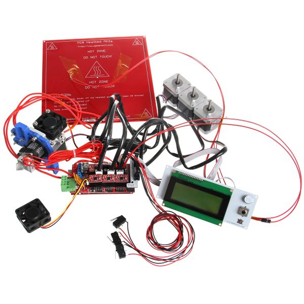
Precautions: Like other electronics, the inverse connection of power supply can cause irreparable damage to the board (4988 included). You are advised to connect all the components before testing.
File Burning
As Ramps1.4 is just the shield board of Mega2560, the firmware must be burned into Mega2560.
Software Setting
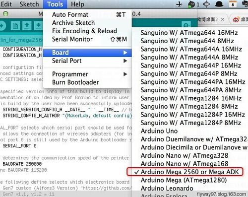
1.Before uploading, driver should be installed for windows. Then choose the type of board: Tools > Board > Arduino Mega 2560 or Mega ADK. (Picture below)
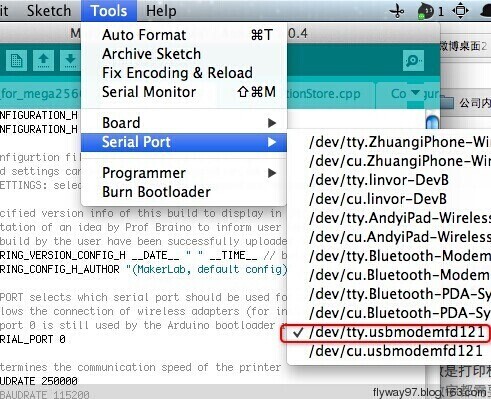
2.Select the serial port: Tools > Serial Port, the serial port for mega is usually the last one.
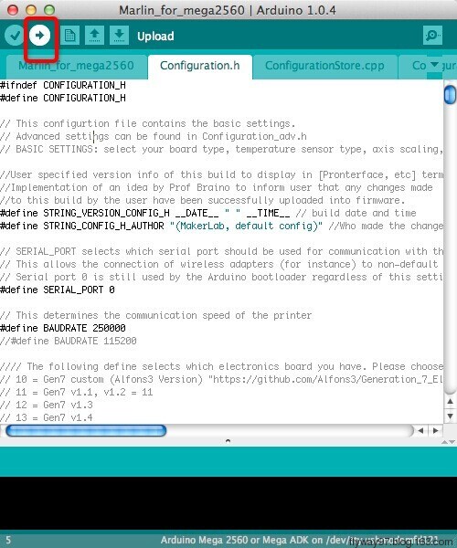
3.Click![]() to check if there is any mistake. If not, click
to check if there is any mistake. If not, click![]() to upload.
to upload.
4.During the process of uploading, the 3 LEDs corresponding to TX, RX and L on mega board will blink, if the blink stops, the uploading is done.
After the uploading, you can go on with the next step. If the uploading is unsuccessful, read the error report on IDE, figure out the problem, and then try again. some frequent errors are: a wrong select of board type and serial port.
The connection of Repetier-Host
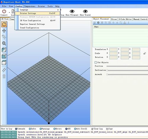
1. Click configuration> printer setting
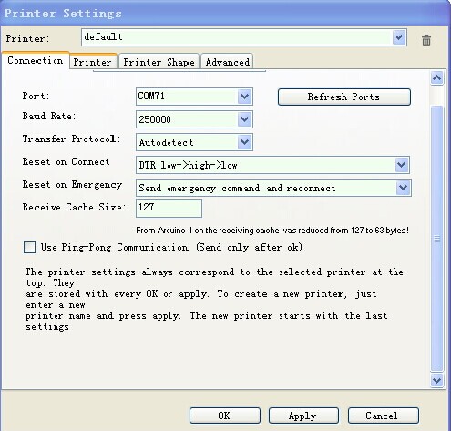
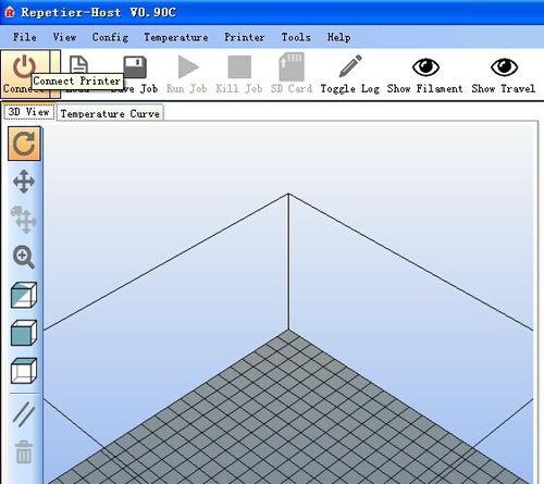
2. Set the communication port (the COM port for mega) and the Baud rate. Then click ok
3. Click “connect”> upload. Choose the GCODE file you are printing.
Get Started
Mega 2560 is the CPU of a 3d printer, manipulating the whole process of printing. Mega 2560 can’t be put in use directly without uploading firmware.
1. Firmware uploading- marlin.
2. Setting parameters of the firmware
3. The parameters that need setting are as below, for those not mentioned just leave them as default.
#define BAUDRATE 250000
This parameter is for the baud rate of serial port. Note: a successful communication can be realized only when the Baud rate of upper computer is identical with that of Firmware. The Baud rate is not set in random. The common Baud rate are: 2400,9600,19200,38400,57600,115200,250000. The last three are frequently used for 3D Printer.
#define MOTHERBOARD 33
This parameter is set for board type. 3D Printer has many types of main board, and the setting of IOs is different, therefore, the parameter has to correspond to the type of your board, or it can’t operate normally. The parameter of mega should be 33(single- nozzle) or 34 (dual-nozzle). For other board, you can refer to the annotation on the board.
  #define TEMP_SENSOR_0 3
  #define TEMP_SENSOR_BED 3
The two parameters are set for the type of temperature sensor respectively. They are the critical parameter to check if the sensor read temperature correctly. The printer can’t operate normally, even has potential risk (damage the device and even worse). You must modify depending on the temperature sensor you use.
#define EXTRUDE_MINTEMP 170
This parameter is set to avoid the potential risks when the extruder operates before reaching the rated temperature. If you use other 3D Printer, such as printer to make Chocolates, 45℃ is appropriate, so that the parameter configured to a lower value(such as 40℃).
  const bool X_ENDSTOPS_INVERTING = true;
  const bool Y_ENDSTOPS_INVERTING = true;
  const bool Z_ENDSTOPS_INVERTING = true.
The three parameters are set for the end stops of three axes. If the configuration is true, the end stop outputs 1 in default condition, and outputs 0 when triggered. That is to say, mechanical end stop should connect to the NO (normally open) contactor. If it is connected to the NC (normally closed), true should be changed to false.
  #define INVERT_X_DIR false
  #define INVERT_Y_DIR true
Mistakes are often made in the above two parameters. The parameters are different for different machinery. In principle, the origin should be at lower-left corner of the print platform (origin: [0, 0]), or at up-right corner (origin: [max, max]). Only in this way will the printing be correct, otherwise, the printing is the mirror image of one axis which is not what expected.
  #define X_HOME_DIR -1
  #define Y_HOME_DIR -1
  #define Z_HOME_DIR -1
If the position of the origin is the minimum, the parameter is -1; if it is the maximum, the parameter is 1.
  #define X_MAX_POS 205
  #define X_MIN_POS 0
  #define Y_MAX_POS 205
  #define Y_MIN_POS 0
  #define Z_MAX_POS 200
  #define Z_MIN_POS 0
These parameters are crucial to the printing size. Fill in parameters by reference to the coordinate graphs. It is important to note that the origin is not the printing center and the real printing center usually lies at [(x.max - x.min)/2, (y.max -y.min/2)]. The coordinate of central will be used in the slice tool. The printing center’s coordinate must correspond to the parameter configuration, or it will print to the outside of the platform.
#define HOMING_FEEDRATE {50*60, 50*60, 4*60, 0}
The parameter means the homing speeds (mm/min). This parameter can be set as default if you use the x-axis and y-axis adopt synchronous belt drive and z-axis adopts screw drive.
#define DEFAULT_AXIS_STEPS_PER_UNIT {85.3333, 85.3333, 2560, 158.8308}
These parameters are crucial to the printing size. These parameters indicate the pulse the axis need when operating 1mm. they are corresponding to x, y, z axis and extruder respectively. In most cases these figure should be calculated by yourself, you can refer to: http://calculator.josefprusa.cz/#steppers.
So far, the commonest parameters have been configured and the printer can work now. In addition, if the 2004 LCD needs verifying, you should delete the “//” from “//#define REPRAP_DISCOUNT_SMART_CONTROLLER” to ensure the normal working.
Extensible Applications
Upload through Bluetooth
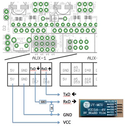
The COM should be set as (9600, N, 8, 1) The command for Bluetooth module:
  AT OK
  AT+BAUD8 OK115200BAUD (set baud rate for RAMPS/Arduino Mega)
  AT+NAMEPRUSAI3 OKsetname (optional set name, default: linvor)
  AT+PIN0000 OKsetPIN (optional set pin, default: 1234)
FAQS
1.How many extruders can ramps support?
Ramps 1.4 support 5 A4988 driving boards, which are for X/Y/Z/axis and 2 extruders respectively, so the ramps can support at most 2 extruders.
2. What should I note when provide power for ramps?
The recommended power supply for Ramps is 12V, especially for Mega2560. If supplied over 12v, Mega will over heat, resulting in instability of operation, the serial port communication is was at times strong and at other times weak. Do make sure the power is 12v, if you don’t have switching power supply of 12v, please take down the diode D1 on Ramps if you use a greater power supply. The current is decided by the use of hotbed. If you use a hotbed, an idea power supply is 12v 17A, 200W. If not, 5A is enough.
3. Can fan be added to Ramps?
Yes. If you use only one extruder, you can connect the fan to the 2 pins in the middle of the 6 blue output pins. If you use two extruders, the fan cannot be connected to ramps directly; you should connect it to a power source that is controlled manually. Or you can build an external circuit, the pins of which should be set in the firmware,
4. What is the difference between ramps and ultimaker?
In the respect of function, they are totally alike. But there are some difference, one lies in the configuration of I/O pins. Another lies in the way of reading temperature. Ultimaker uses thermocouple and temperature control board (AD597), ramps uses NTC thermistor 100K. If you want to use thermocouple and temperature control board for ramps, you should take down the pull-up resistor one the thermistor of hot end.
5. Can Ramps replace ultimaker to make an ultimaker printer?
Yes, it can, but you need to pay attention to the points we’ve mentioned in chapter Ⅴ .The ultimaker printer is one kind of reprap, as well as standard three- axis rectangular coordinates
6. The temperature displayed is not normal.
A. you may select the wrong thermistor in marlin, we often choose 1.
B. The thermistor is Brocken or there is short-circuit occurred in the 2 pins of the thermistor.
C. The electrolytic capacitor on ramps is broken.
7. The motor jitters.
A. It is a matter of poor connection,
B. A4988 has broke down,
C, the VREF is not right.
8. The scope of motor is too small.
You may forget putting the jumper cap, or the parameter you set is wrong.
9. The program uploading is not successful.
The USB cable doesn’t work; the version of Arduino IDE you use is not compatible; the select of COM is wrong.
10. The hotbed and extruder can’t heat.
A. The MOSFET is broken.
B. The thermistor is not connected.
11 the motor of extruder doesn’t work.
The thermistor is not connected; the temperature is not enough; A4988 broke down; ramps 1.4 broke down.
where to get
ckick here to get your ramps 1.4
