Difference between revisions of "Spark E3"
(→1Uncontrollable fan interface) |
(→Firmware Upgrade) |
||
| Line 165: | Line 165: | ||
The Spark E3 V1.0 mainboard supports the use of TF card to upgrade the firmware. When using the TF card to upgrade the firmware, the firmware must be placed in the root directory of the TF card. The name of the firmware must be "GTM32Source.bin", otherwise it cannot be upgraded. | The Spark E3 V1.0 mainboard supports the use of TF card to upgrade the firmware. When using the TF card to upgrade the firmware, the firmware must be placed in the root directory of the TF card. The name of the firmware must be "GTM32Source.bin", otherwise it cannot be upgraded. | ||
| + | |||
| + | There are two kinds of firmware, one with 3d touch and one without 3d touch.Firmware download address:https://www.geeetech.com/download.html?download_id=40 | ||
Latest revision as of 08:39, 21 June 2023
Contents
- 1 Introduction
- 2 Interface Description
- 2.1 Power Input
- 2.2 Hot end heating rod power supply
- 2.3 Hot bed power output
- 2.4 Hot bed temperature sensor (NTC)
- 2.5 Hot end temperature sensor (NTC)
- 2.6 Limit switch
- 2.7 Filament sensor interface
- 2.8 3D-Touch interface
- 2.9 Controllable fan interface
- 2.10 Uncontrollable fan interface
- 2.11 LCD12864 screen interface
- 2.12 Serial screen interface
- 2.13 RGB light interface
- 2.14 USB interface
- 2.15 USB Powered
- 2.16 Microstep Resolution
- 2.17 A4988 module instructions
- 2.18 TMC2208/TMC2209 Module Instructions
- 2.19 TMC2209 sensorless function
- 2.20 LCD screen interface
- 2.21 Color touch screen interface
- 3 Mainboard LED
- 4 Firmware Upgrade
Introduction
Spark E3 V1.0 is an upgrade kit specially launched by the R&D team of Shenzhen Getech Technology Co., Ltd, which can perfectly replace the original motherboard of Ender3 series printers.
User Mannal
Please click here to download.https://www.geeetech.com/download.html?download_id=40
Features
Compared with other motherboards of the same type, Spark E3 V1.0 has the following features:
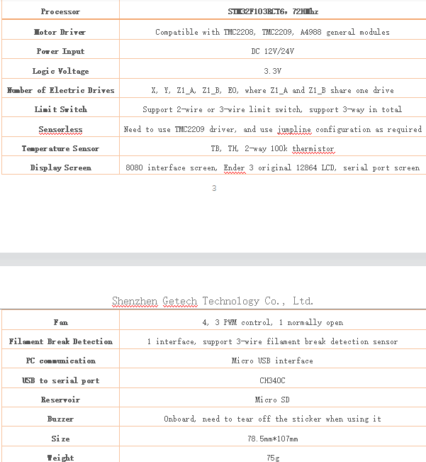
1)The main control chip adopts ARM Cortex M3 32-bit STM32F103RCT6, the main frequency is up to 72MHz.
2)The 4 stepper motor drivers are designed with pluggable modules. Compared with the onboard motor drivers, users can replace the drivers by themselves.
3)Support A4988, TMC2208 and TMC2209 three common driver modules.
4)Support TMC2209 Sensorless function.
5)The limit switch interface is compatible with 3-wire photoelectric limit switch.
6)Support 8080 interface touch screen.
7)4-way fan interface, 3-way PWM control, one normally-open-fan interface.
8)The main board supports functional extension modules such as 3D-Touch, Neopixel light strip, shutdown-after-printing module, material breakage detection module, and power-off protection module.
9)The hot bed and hot end adopt ultra-high current MOS tube, which is more durable and not easy to damage.
Hardware specifications
Interface Description
Power Input
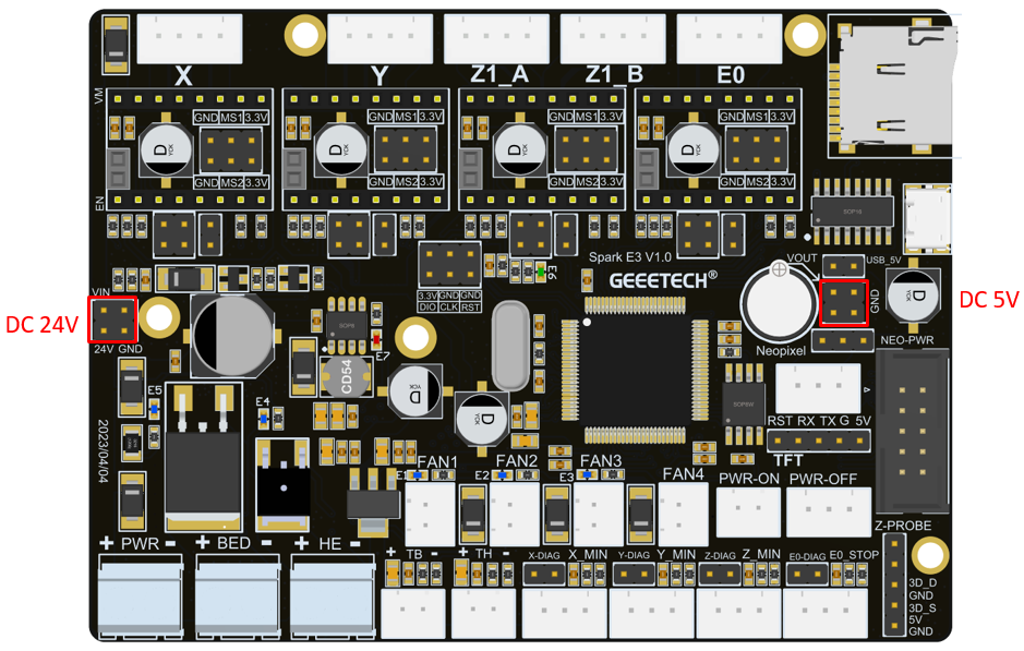
The Spark E3 V1.0 motherboard supports 12V or 24V DC power supply. It should be noted that when using 12V direct power supply, the corresponding fans and heating rods need to be replaced with 12V power supply specifications. When connecting the power cord, please note that the positive and negative poles of the typical power supply cannot be connected incorrectly.
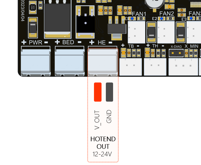
Hot end heating rod power supply
Spark E3 V1.0 heating rod is controlled by WSF3085 MOS tube, it can support a maximum output of 24V/85A. It is recommended to use a heating rod with appropriate power to ensure safe use.
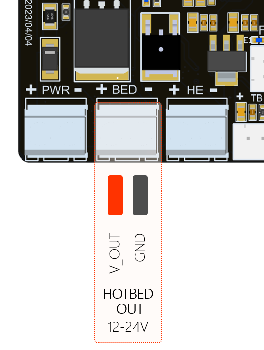
Hot bed power output
Spark E3 V1.0 heating bed power supply is controlled by WSK220N04 MOS tube, supports 24V maximum current output of 220A, but we recommend not to use more than 250W heating bed to ensure safe use. High-power hot bed means that a more powerful power supply must be used, which cannot effectively improve the user experience when using a 3D printer.
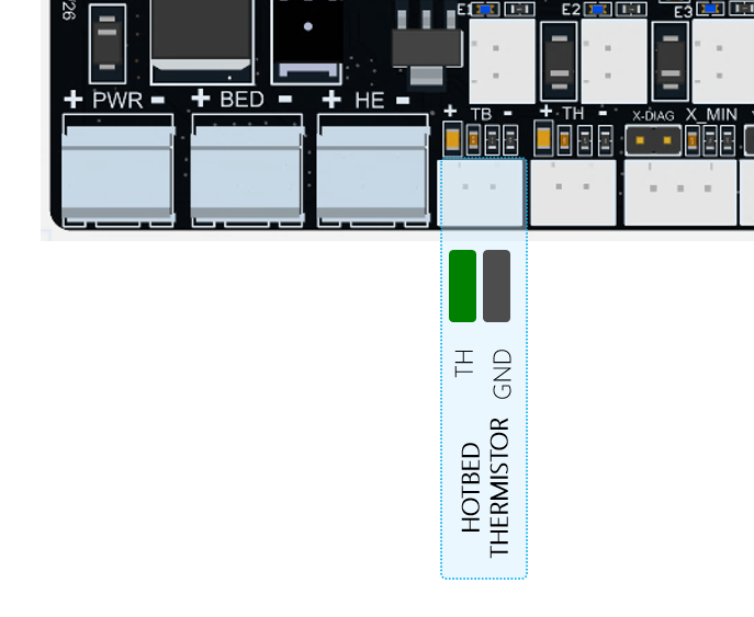
Hot bed temperature sensor (NTC)
The Spark E3 V1.0 hot bed temperature sensor uses a 100k thermistor by default. The open source firmware we provide uses a 100k thermistor by default. If you want to use other specifications, you need to modify the relevant parameters in the code,the hot bed temperature sensor on the main board uses 2 pins and a connector with a spacing of 2.54mm.
Hot end temperature sensor (NTC)
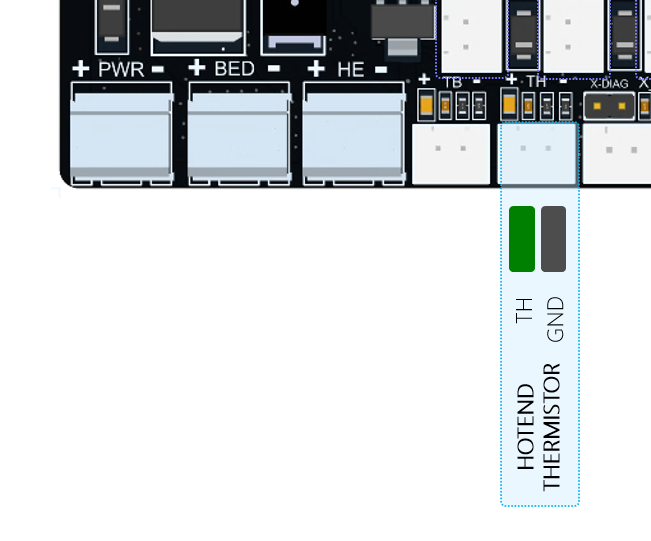
Spark E3 V1.0 hot-end temperature sensor supports 100k thermistor by default. The open source firmware we provide uses 100k thermistor by default. If you want to use other specifications, you need to modify the relevant parameters in the code. As shown in Figure, the hot-end temperature sensor on the main board adopts 2 pins and a connector with a pitch of 2.54mm.
Limit switch
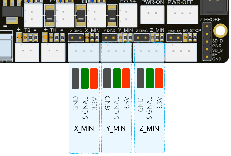
Spark E3 V1.0 supports 3 limit switches, X_Min, Y_Min, Z_Min. Each interface has 3 wires, they are 3.3V, GND, signal input (X_Min, Y_Min, Z_Min), where X_Min , Y_Min, Z_Min have 4.7K pull-up resistors by default. As shown in Figure, the upper limit switch on the main board adopts 2 pins and a connector with a spacing of 2.54mm;
Filament sensor interface
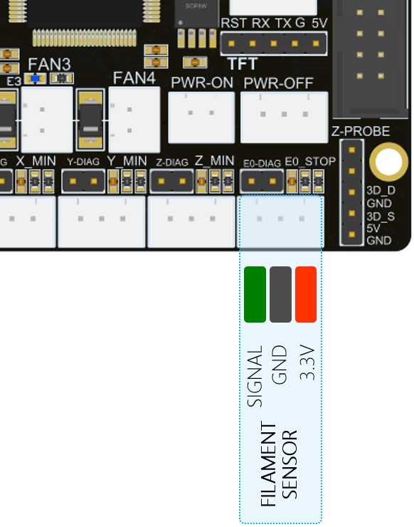
The Spark E3 V1.0 filament sensor interface supports a 3-wire filament detection sensor. The definitions of the three wires are 3.3V, GND, and signal input (E0_DET).
As shown in Figure, the interface of the filament detection sensor on the main board adopts 3 pins and a connector with a spacing of 2.54mm.
3D-Touch interface
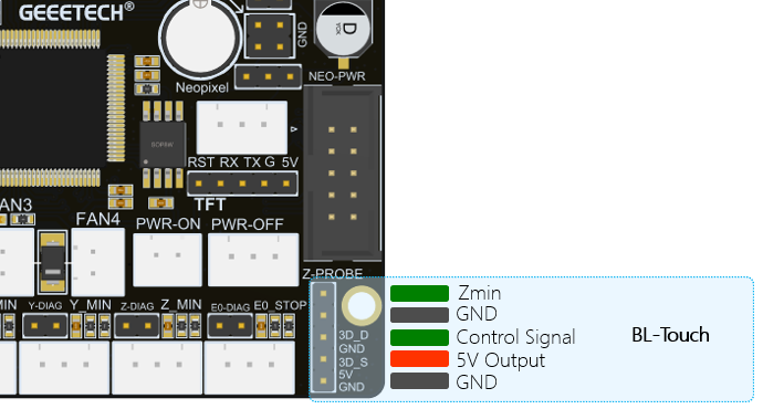
Spark E3 V1.0 reserves a 3D-Touch interface, which can be connected to GEEETECH 3D-Touch sensor or BL-Touch and other similar leveling sensors, as shown in Figure. The interface definition is as follows:
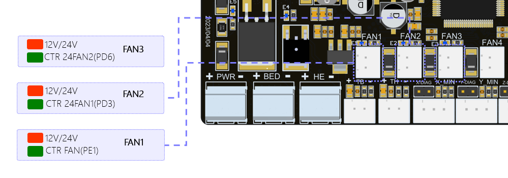
Controllable fan interface
9)Spark E3 V1.0 reserves three PWM control fan interfaces, FAN0, FAN1, and FAN2. All three fan interfaces on the circuit are controlled by WST6066A MOS tubes, and can output a maximum current of 2.1A, which can allow users to connect high-power fans. At the same time, a yellow LED is designed on each fan interface, which is convenient for users to observe the working status of the fan. When the fan is working, the LED will start to flash, and if the fan stops, the LED will be off. In the firmware we provide, FAN0 is defined as Part Cooling Fan.
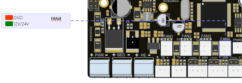
Uncontrollable fan interface
On the Spark E3 V1.0 motherboard, FAN3 is a 24V normally open fan interface, which is used to connect the throat pipe cooling fan.
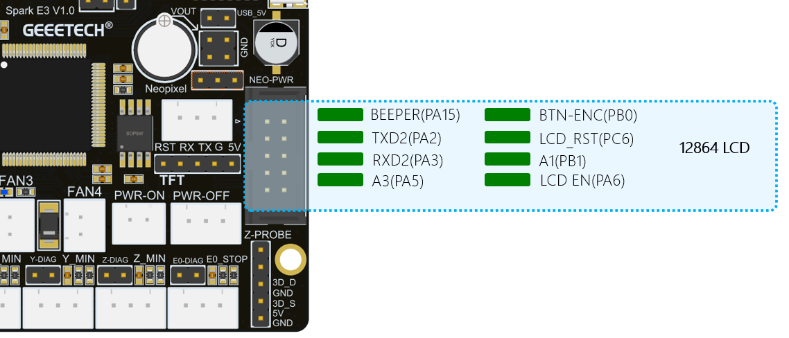
LCD12864 screen interface
There is an LCD12864 screen interface on the Spark E3 V1.0 motherboard, and you can directly use the original LCD12864 screen of Ender3. The definition of the pin on screen interface is shown in Figure:
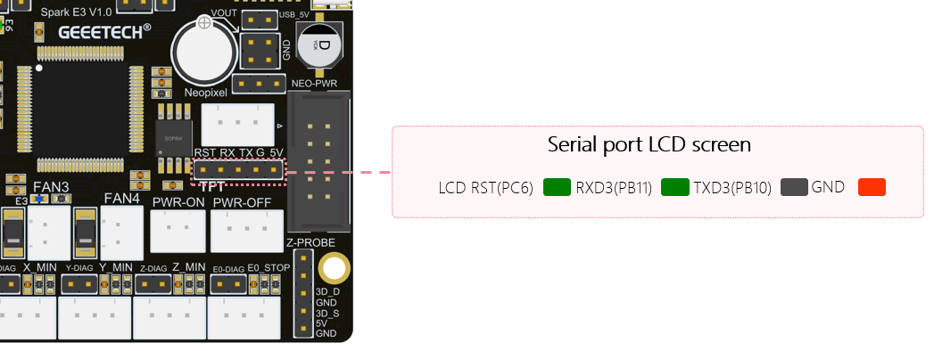
Serial screen interface
The Spark E3 V1.0 motherboard reserves a serial port screen interface, which supports LCD screens powered by 5V. Currently, the motherboard is not compatible with serial port screens. The definition of the serial screen interface is shown in Figure, where RST is used to reset the serial screen.
RGB light interface
The Spark E3 V1.0 motherboard reserves a Neopixel light strip interface, which can provide a maximum load capacity of 5V/1.5A. When using it, the power of the light strip should not exceed 7.5w. Otherwise, the power supply of the mainboard will be unstable or the mainboard will be nonfunctional. The definition of light interface is shown in Figure:
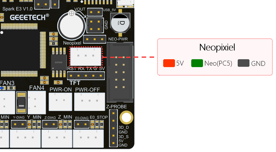 That when using Spark E3 V1.0 to supply power to the main board, the jumper cap needs to be connected as shown in Figure, so that the 5V power supply of the main board can be used to power the light strip.
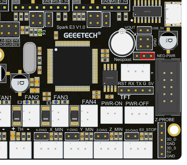 If the user wants to use more light strips, needing to purchase the extension module Spark DC 5V specially set by GEEETECH for high-power waiting. This extension module can provide an output current up to 5A. When using the Spark DC 5V module, the jumper cap needs to be connected as shown in Figure:
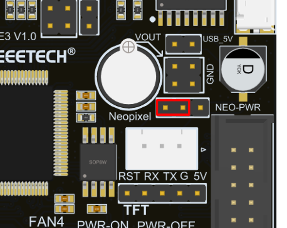 The Spark DC 5V module needs to be plugged into the corresponding pin header on the motherboard, as shown in Figure:
USB interface
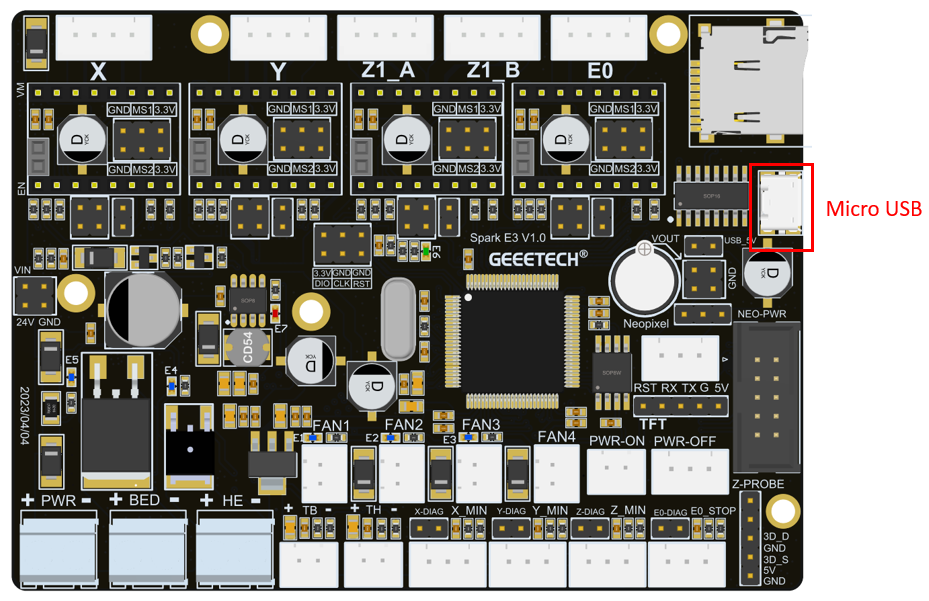
Spark E3 V1.0 motherboard has designed a Micro USB physical interface, as shown in Figure, which is used to connect to the PC USB interface for online printing. The interface uses the CH340C chip. If the serial port cannot be recognized during online printing, the user can download the driver of this chip from the Internet and then install.
USB Powered
In order to facilitate the user's debugging, Spark E3 V1.0 has designed the motherboard power supply switch. When debugging the motherboard, the user can directly get power from the USB through the jumper cap, as shown in Figure. It can be used without using AC 115V/230V. The specific jumper settings are shown in the figure below:
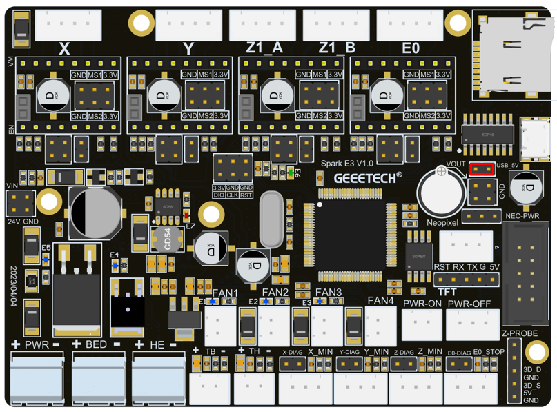 That it is recommended to unplug the jumper cap when using the switching power supply, or the 3D printer cannot be turned off while printing online.
Microstep Resolution
A4988 requires MS1, MS2 and MS3 to adjust the Microstepping Resolution, Spark E3 V1.0 MS3 The default 10k pull-up resistor. TMC2208 and TMC2209 only need MS1 and MS2 to adjust the Microstepping Resolution.
Figure 1 is the truth table of A4988 Microstepping Resolution.
Figure 2 is the truth table of TMC2208 Microstepping Resolution.
Figure 3is the truth table of TMC2209 Microstepping Resolution.
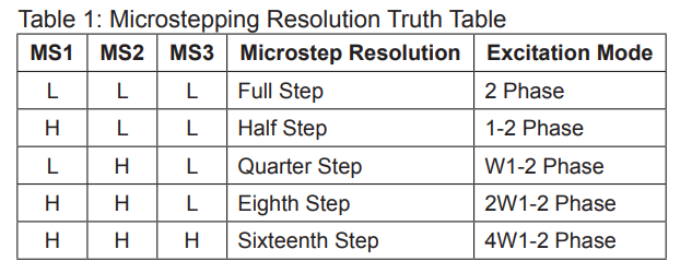

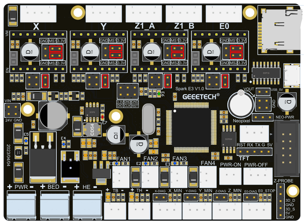
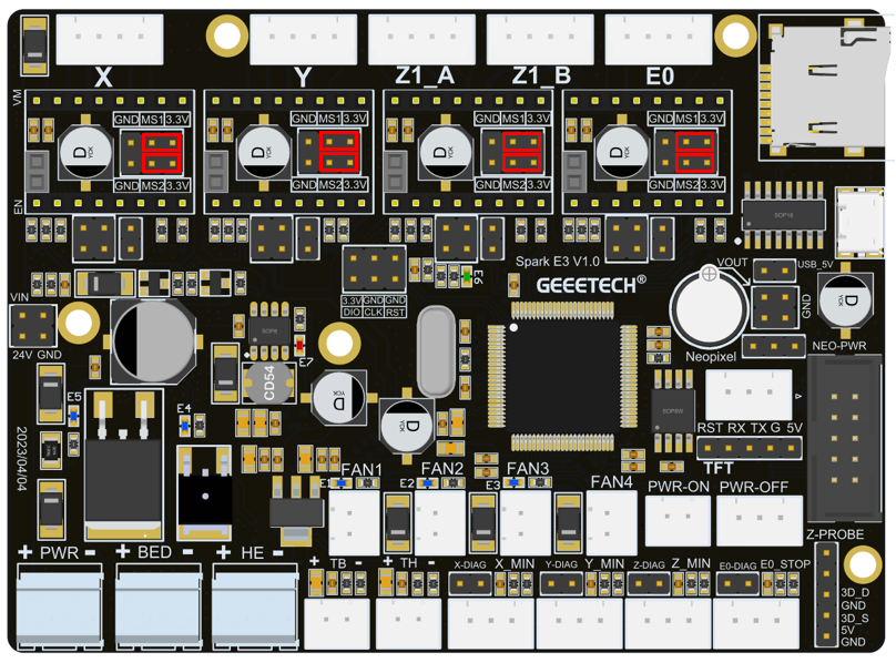
 The jumper position of the spark E3 V1.0 driver module subdivision setting is shown in Figure:
A4988 module instructions
If you want to use the A4988 module, you need to connect the jumper cap as shown in Figure, so that the A4988 module can work normally.
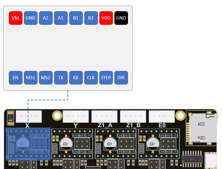
 Before installing the driver module, you must pay attention to the correct correspondence between the pins of the module and the main board before installation. It is strictly forbidden to install with the color of the plastic connector of the module. The definition of the driver module socket on the main board is shown in Figure:
TMC2208/TMC2209 Module Instructions
If you want to use the TMC2208/TMC2209 module, you need to connect the jumper cap as shown in Figure, so that the TMC2208/TMC2209 module can work normally.
TMC2209 sensorless function
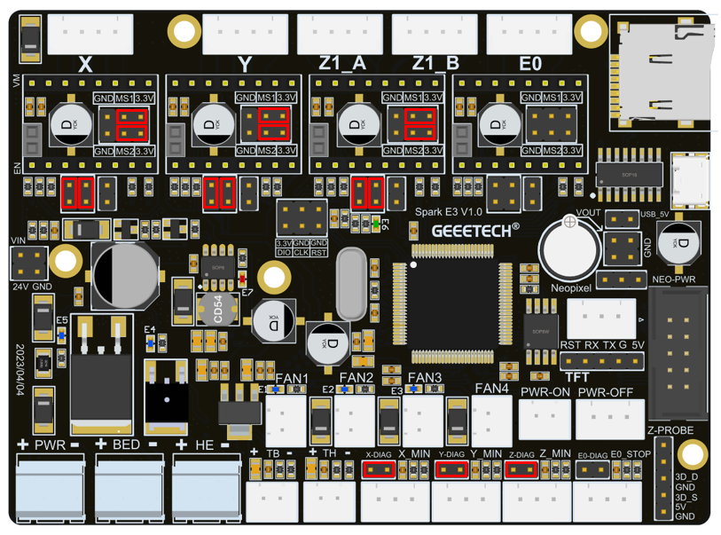
The Spark E3 V1.0 motherboard supports the sensorless function when using the TMC2209 driver module. To use the sensorless function, first remove the limit switches of the three axes of X_min, Y_min, and Z_min, and then install jumper as shown in Figure.
LCD screen interface
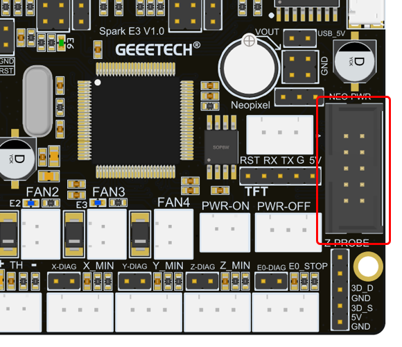
The Spark E3 V1.0 motherboard supports the 12864 original screen of the Eender3 series, and the original screen can be directly connected to the Spark E3 V1.0 motherboard, as shown in Figure.
Color touch screen interface
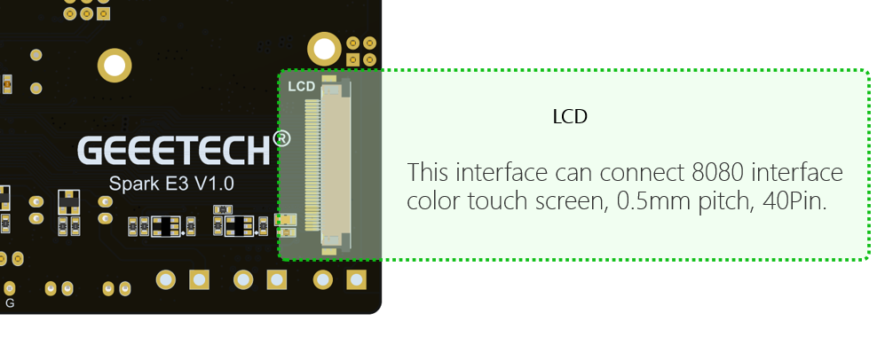
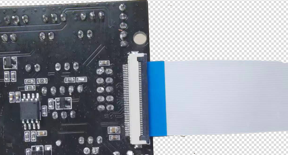
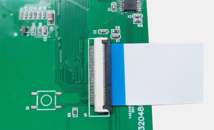
Spark E3 V1.0 has designed an 8080 color touch screen interface, which is connected by a 0.5mm pitch and 40Pin flexible cable. Users can purchase this screen component when purchasing the motherboard.
Mainboard LED
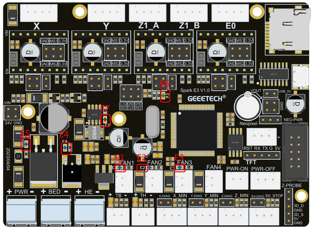
There are a total of 6 LEDs on the Spark E3 V1.0 motherboard. They are identified as E1, E2, E3, E4, E5, and E6 on the motherboard, as shown in Figure. Their definitions are as follows:
1) E1, yellow, indicates the running status of the FAN0 fan. When the FAN0 fan is not connected or is not running, E1 is off. When the FAN0 fan starts to run, the PWM signal of the FAN0 fan will drive E1 to start flashing.
2) E2, yellow, indicates the running status of the FAN1 fan. When the FAN0 fan is not connected or is not running, E1 is off. When the FAN1 fan starts to run, the PWM signal of the FAN1 fan will drive E2 to start flashing.
3) E3, yellow, indicates the running status of the FAN0 fan. When the FAN2 fan is not connected or is not running, E3 is off. When the FAN2 fan starts to run, the PWM signal of the FAN2 fan will drive E3 to start flashing.
4) E4, yellow, indicates the status of the heating rod at the hot end. When the heating rod is not connected or is not heated, E4 is off. When the heating rod starts to heat, the PWM signal of the heating rod will drive E4 to start flashing.
5) E5, yellow, indicates the working status of the hot bed. When the heating rod of hot bed is not connected or is not working, E5 is off. When the hot bed starts to heat, the PWM signal of the hot bed will drive E5 to start flashing.
6) E6, green, MCU power indicator, when the main board is powered on, E6 will always be on if the 3.3V power supply of the MCU is normal.
7) E7, red, 5V power indicator light, when the main board is powered on, E7 is always on.
Firmware Upgrade
The Spark E3 V1.0 mainboard supports the use of TF card to upgrade the firmware. When using the TF card to upgrade the firmware, the firmware must be placed in the root directory of the TF card. The name of the firmware must be "GTM32Source.bin", otherwise it cannot be upgraded.
There are two kinds of firmware, one with 3d touch and one without 3d touch.Firmware download address:https://www.geeetech.com/download.html?download_id=40
