Rumba
Contents
Introduction
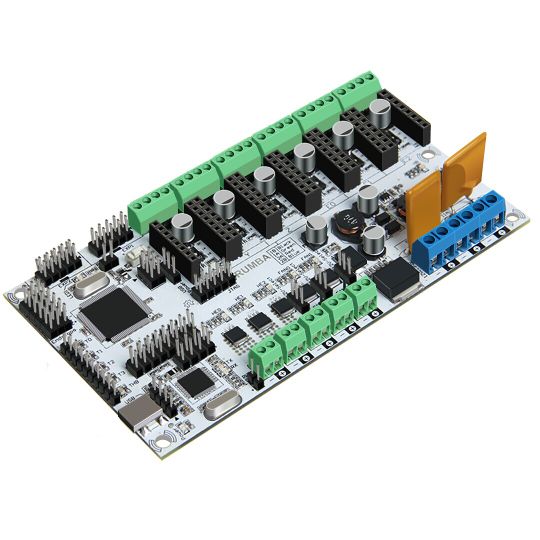
As the core of 3D printer, Rumba’s running is controlled by electric part. Rumba uses the integrated control board on the base of ATmega’s AVR processor. The circuit board is developed for 3D printer, carver, laser cutter and other CNC. Controlling the 3Dprinter with USB or printing through SD memory card. With integrated design, it is easy to install and debug. Using Arduino IDE as the development software, the firmware update and parameter configuration are both easy to use. Compared with other 3D Printer control board, Rumba has one more motor driver and less plug-in part so that it can improve the connectivity and stability. Detailed parameters are as follows.
1 Use the same CPU as that of Arduino MEGA as main control chip, Atmega2560 cooperates with high-performance USB chip in order that it is compatible with all RAMPS relevant firmware;
2 Five interfaces as input for temperature sensor.
3 All pins being drawn out to permit more function expansion.
4 With expanding interface, it can connect the LCD displayed and the development board.
5 Servo’s expanding interface to make the automatic leveling easier to add
6 Supporting 6 pieces of 16 micro stepping drivers of A4988.
7 PWM DC output( heating pipe ,fan), six channels of output( 1 channel of high current, 3 channels of medium current and 2 channels of low current). Use low on-resistance MOS Varactor as driver and LED tests each output.
8 Power-supply: power input 12v-35v, dual power to avoid interaction; hot bed connects 11A, 12V, other sections connect 5A, 12V and add a 12V cooler to reduce the high temperature from the high current of Mega controller.
9 Adopt the popular control board firmware-Marlin, which has good stability, usability and function.
Appearance and Hardware Resources
Size: 135*175mm
Weight: 90g
Software Resources
Interface Resources
Interface Resources Instruction
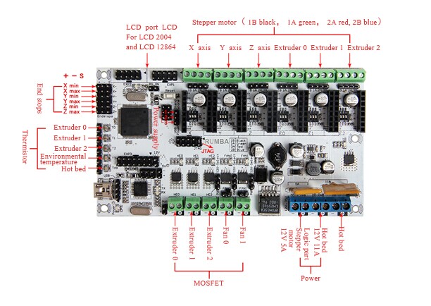
1. Five interface for temperature measurement: three for extruders, one for hot bed and one for environment.
2. Five PWM: three for the heating of extruder and hot bed, one for Fan rotation and one for lighting.
3. Six end stops: Xmin/Xmax/Ymin/Ymax/Zmin/Zmax, which can connect ends tops of machinery and optics or the Hall Sensor.
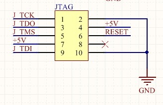
4. Supporting JTAG makes it possible to conduct software development.
Jumper Instruction
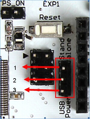
1. MCU power options: connect the jumper cap of 1 and 2 to provide external power. Connect the jumper cap of 2 and 3 to provide USB power.
2. Pulling out Jumper cap to make MCU into Mode DFU
Setting up Operational Environment
Interface Connecting and Setting
File Program
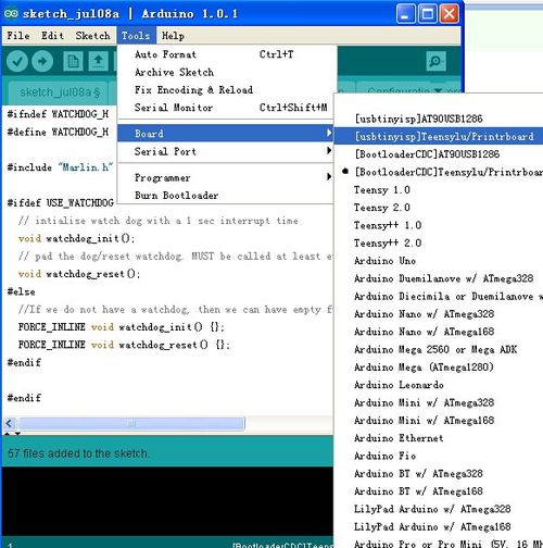
1,Windows users need install driver before uploading. The board: Tools > Board > Arduino Mega 2560 or Mega ADK as shown below.
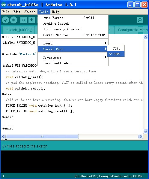
2,Configuring serial interface: Tools > Serial Port > your corresponding Comm Port of mega board of is the last one usually.
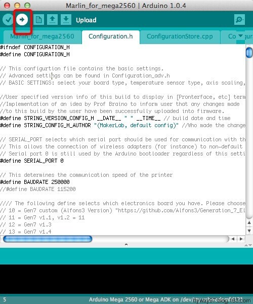
3,Click the “check (![]() )” button to check if it is right or wrong and then click the “
)” button to check if it is right or wrong and then click the “![]() ” button to upload firmware.
” button to upload firmware.
4,Upon uploading the correspondent LED to TX, RX and L will blink, if they stop blinking, the uploading completed.
After uploading, you could go on to the next step. If you cannot upload, check the dialog box below IDE to identify the problem and solve it. The common mistakes of board type include the select error, serial port selection error, etc.
Setting Software
for more detailed insturction, please refer to the user manual.
Arduino IDE Installation
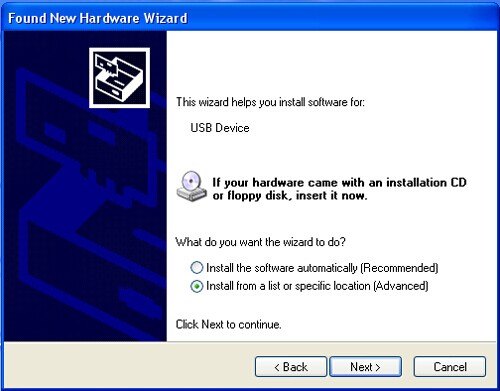
1,You can notice USB identification “Arduino Mega 2560” on your computer when connecting the Rumba to computer with USB.
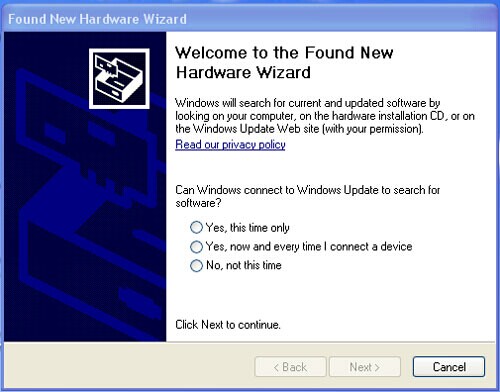
Then, windows will open the dialog box “found new hardware guide”, check “no, not this time”, then click “next”.
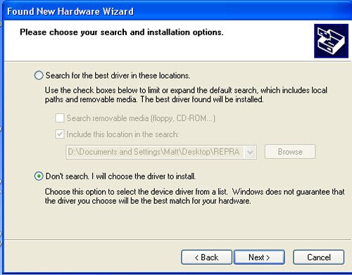
2,Check “install from lists or specific location (advanced)”, then click “next”.
3, Specify “drivers” in Arduino 0021 installation directory to install driver.
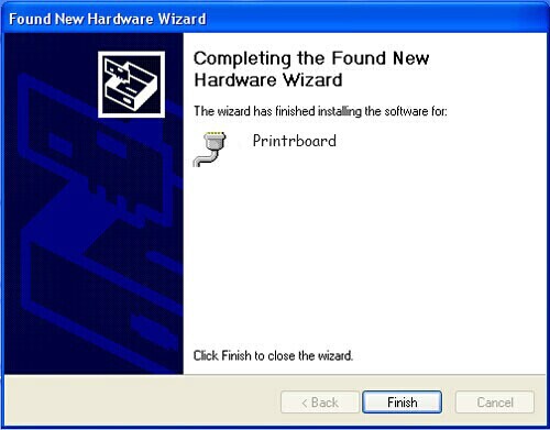
If every goes well, windows will install the corresponding driver.
The graph below shows installation completed.
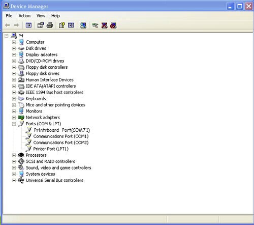
At this time we could find the corresponding Arduino MEGA 2560 device in device manager of windows.
Quick Started Guide to program
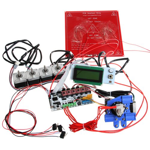
Rumba board to 3D printer is just like the brain to human. Rumba fulfill the complicated printing through dominating all 3D Printer Accessories。It cannot operate directly without uploading firmware.
1.Download firmware-Marlin. Marlin firmware is born with powerful features and easy to use, therefore we just introduce Marlin firmware.
2.Configure Firmware parameter.
The following parameter need configured, others default.
#define BAUDRATE 250000
It configures for SERBAUD. Note: the successful communication can be realized when the upper computer Baud rate is identical with Firmware Baud. The Baud can’t be modified freely. The common Baud : 2400,9600,19200,38400,57600,115200,250000. The last three are frequently used by 3D Printer.
#define MOTHERBOARD 80
The parameter is used to configure board type. 3D Printer has many types of main board, but the IOs of all boards are different, therefore, the parameter has to correspond to the type of your board, or it can’t operate normally. The configuration of Rumba should be 80(single nozzle configuration). If it is other board, you can choose a suitable parameter with the annotation beside the board.
 #define TEMP_SENSOR_0 3
 #define TEMP_SENSOR_BED 3
The two parameters configure the type of temperature sensor respectively. They are the critical parameter to check if the sensor read temperature normally. It is can’t operate even has potential risk (burn the device and others) when the temperature readout is normal. You must modify depends on circumstance if you used other temperature sensors.
#define EXTRUDE_MINTEMP 170
The parameter is to avoid the potential risks when the extrusion operates before reaching the appropriate temperatures. If it is used for other 3D Printer, such as printer of Chocolates, 45℃ is appropriate, so that the parameter configured to a lower value(such as 40℃).
 const bool X_ENDSTOPS_INVERTING = true;
 const bool Y_ENDSTOPS_INVERTING = true;
 const bool Z_ENDSTOPS_INVERTING = true.
The three parameters configure the end stops types of three axes. The configuration is true, the end stop outputs 1 in default condition and outputs 0 in trigger condition. That is, mechanical end stop connects the AOF. If it connects the AON, true should be changed to false.
 #define INVERT_X_DIR false
 #define INVERT_Y_DIR true
It is easily to make mistakes in the above two parameters. The parameters are different in different machinery. However, in principle, the origin should be at lower-left corner of the print platform (origin: 0, 0), or at up-right corner (origin: max, max).then, the model printed is correct, otherwise, the printed is the mirror image of one axis, with the result that the wrong model direction.
 #define X_HOME_DIR -1
 #define Y_HOME_DIR -1
 #define Z_HOME_DIR -1
If the origin is the minimum, the parameter is -1; if it is the maximum, the configuration is 1.
 #define X_MAX_POS 205
 #define X_MIN_POS 0
 #define Y_MAX_POS 205
 #define Y_MIN_POS 0
 #define Z_MAX_POS 200
 #define Z_MIN_POS 0
These parameters are crucial to the printing size configuration. Fill in parameters by reference to the coordinate graphs. It is important to note that the origin is not the printing center and the real printing center usually at [(x.max - x.min)/2, (y.max -y.min/2)]. The coordinate of central position will be used in the slice tool. The printing center’s coordinate must correspond to the parameter configuration, or it will print to the outside of the platform.
#define HOMING_FEEDRATE {50*60, 50*60, 4*60, 0}
The rate of configuration back to origin, unit: mm/min. This parameter could be set default when you use the x-axis, y-axis synchronous belt drive and z-axis screw drive.
#define DEFAULT_AXIS_STEPS_PER_UNIT {85.3333, 85.3333, 2560, 158.8308}
These parameters are crucial to check if the printing size is correct. Parameters means that the pulse number needed at every axis when operating 1mm. they are correspond to x, y, z and e respectively. In most cases these number should be computed by yourself, but you can refer to: http://calculator.josefprusa.cz/#steppers So far we have configured the common parameters and could operate it. In addition, if the 2004LED need verifying, you should delete the “//” from “//#define REPRAP_DISCOUNT_SMART_CONTROLLER” to ensure the normal working.
Extensible Applications
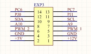
Exp: IIC、PWM、GPIO
JTAG:
FAQS
1. Q: The LED light is off when connected USB and external 5V power.
a. The jumper cap of MCU power options has not plugged.
b.The LED does not work or not weld correctly.
2. Q: LCD screen does not display.
A: The code has not burned-in and the connection of LCD is poor.
3. Q: Fail to install driver.
A: you may encounter a problem “system cannot find the specific folder” in the process of Arduino driver installation when you use starter edition windows, because the starter edition of windows system has deleted some uncommon information for driver. The resolutions are as follows,
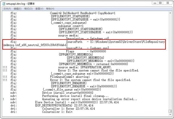
A: open C:\windows\inf\setupapi.dev.log The file not only includes plug and play device, information for driver installation, but also record the reason for the failure of Arduino driver installation. Open this file and move to the end of the file you will observe the following information as in the flowing picture.
It is just the file error that causes the failure of Arduino driver installation.
B: creating a folder” mdmcpq.inf_x86_neutral_******** “in the path of
C:\Windows\System32\DriverStore\FileRepository\
The identifications of all computers are different, so please refer to the prompt box from the “setupapi.dev.log” to know the “******* “. For example, information provided by my computer is
“C:\Windows\System32\DriverStore\FileRepository\mdmcpq.inf_x86_neutral_9f203c20b6f0dabd “
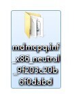
According to this prompt, I created another folder with the same name in the path of C:\Windows\System32\DriverStore\FileRepository\, as follows,
C: Download and decompress the following file and add it to the created folder mdmcpq.inf_x86_neutral_********. 32bits windows:
D. Reinstall driver step-by-step.
At this point, driver can be installed.
If the computer system is windows 8 and driver cannot be installed, there are some other alternative methods for you.
Click Windows and R
Input shutdown.exe /r /o /f /t 00
Click “confirm”
The system enters “option” page automatically
Click FAQ
Click advanced options
Click windows boot settings
Click reboot button
System will reboot and go to the advanced boot options
Click “disable driver and mandatory signature”
Rebooted, install the Arduino driver and the installation method is the same with that of windows 7.
How to buy
Click here to buy: http://www.geeetech.com/geeetech-rumba-the-latest-3d-printer-controll-board-p-848.html
