Difference between revisions of "Robot Aduino With Atmega328"
From Geeetech Wiki
| Line 23: | Line 23: | ||
== Schematic / Eagle Files: == | == Schematic / Eagle Files: == | ||
| − | + | [Roboduino v1.15 - 1.16 schematic http://store.curiousinventor.com/media/images/kits/roboduino/roboduino_v1_16_schematic.pdf] | |
== Example Code == | == Example Code == | ||
| − | + | [http://store.curiousinventor.com/media/images/kits/roboduino/RoboduinoDemo.pde Example Code] | |
| − | |||
Revision as of 02:38, 17 March 2012
Description
The Roboduino is a Freeduino (Arduino software compatible) microcontroller board designed for robotics. All of its connections have neighboring power buses into which servos and sensors can easily be plugged. Additional headers for power and serial communication are also provided. The kits come with the surface mount parts pre-soldered. Skill level: Beginner to intermediate.
Features
- 100% Compatible with Arduino software.
- Power buses along side pwm and analog pins easily accept standard servo and sensor connectors.
- Powered can be supplied from USB, barrel plug or 3-pin male header. You'll need a suitable power supply when driving multiple servos.
- Dedicated UART 3-pin male header
- 6 PWM outputs with neighboring unregulated power pins
- 6 analog pins
- 14 digital pins
- Reverse polarity protection for board circuitry (not for unregulated power pins)
- Optional I2C pull-up resistor locations
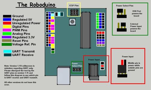
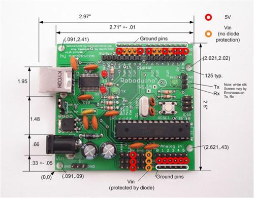
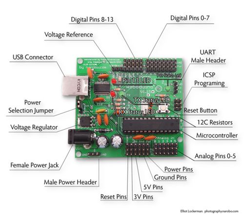
Roboduino Diagrams:
Schematic / Eagle Files:
[Roboduino v1.15 - 1.16 schematic http://store.curiousinventor.com/media/images/kits/roboduino/roboduino_v1_16_schematic.pdf]


