PIXHAWK
Introduction
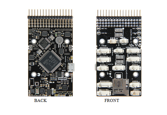
PIXHAWK is an advanced autopilot system of 3DR. It features transparent for hardware and convenient for re-development. PIXHAWK integrates with two advanced processor, STM32F103 backup failsafe 32-bit co-processor provides for manual recovery and has its own power supply if one processor breaks down, delivering incredible performance, flexibility, and reliability for controlling any autonomous vehicle. Users can also adjust the configurations of PIXHAWK according to different use and hobbies for different vehicles. In recent years, as one of the cores of autopilot system, PIXHAWK has gained a profound popularity among developers and hobbyists for being practical, easy to handle, economical.
Features
- Advanced 32 bit ARM Cortex® M4 Processor running NuttX RTOS (68 MHz / 252 MIPS Cortex-M4F) real-time operating system.
- 14 PWM/servo outputs (8 with failsafe and manual override, 6 auxiliary, high-power compatible)
- Abundant connectivity options for additional peripherals (UART, I2C, CAN)
- Integrated backup system for in-flight recovery and manual override with dedicated processor and stand-alone power supply
- Backup system integrates mixing, providing consistent autopilot and manual override mixing modes
- Redundant power supply inputs and automatic failover
- External safety button for easy motor activation
- Multicolor LED indicator
- micro-SD card for long-time high-rate logging
Overview and Hardware Resources
Dimension: 81.5 mm*50mm*15.5mm
Net weight: 38.4g
Specifications
3 Microprocessors:
- 32-bit STM32F427 Cortex M4 core with FPU
- 168 MHz/256 KB RAM/2 MB Flash
- 32 bit STM32F103 failsafe co-processor
4 Sensors:
- ST Micro L3GD20 3-axis 16-bit gyroscope
- ST Micro LSM303D 3-axis 14-bit accelerometer / magnetometer
- Invensense MPU 6000 3-axis accelerometer/gyroscope
- MEAS MS5611 barometer
10 Interfaces:
- 5x UART (serial ports), one high-power capable, 2x with HW flow control
- 2x CAN
- Spektrum DSM / DSM2 / DSM-X® Satellite compatible input up to DX8 (DX9 and above not supported)
- Futaba S.BUS® compatible input and output
- PPM sum signal
- RSSI (PWM or voltage) input
- I2C®
- SPI
- 3.3 and 6.6V ADC inputs
- External micro-USB port
Power System:
- Ideal diode controller with automatic failover
- Servo rail high-power (7 V) and high-current ready
- All peripheral outputs over-current protected, all inputs ESD protected
Software Resources
Firmware loading:MissionPlanner
Host software:MissionPlanner
Plug-in:Net Flamework 4
Interfaces
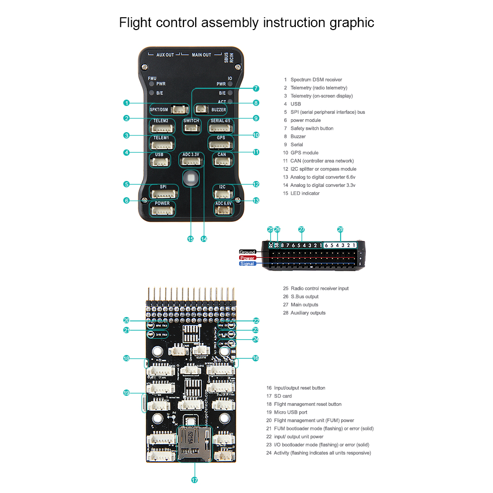
Interface Layout
Interface specifications
1. Connect a PWM RC receiver to PIXHAWK.
2. Connect the ground (-), power (+), and signal (S) wires to the RC pins using the provided 3-wire servo cable.
LED Indication
Flashing red and blue: initializing. Please wait.
Double flashing yellow: error. System refuses to arm.
Flashing blue: disarmed, searching for GPS. Autonomous, loiter, and return-to-launch modes require GPS lock.
Flashing green: disarmed, GPS lock acquired. Ready to arm;Quick double tone when disarming from the armed state.
Solid green plus single long tone: armed and ready to fly!
Flashing yellow: RC failsafe activated.
Flashing yellow plus quick repeating tone: battery failsafe activated
Flashing yellow and blue plus high-high-high-low tone: GPS glitch or GPS failsafe activated
Development Environment setting
Interface Connecting and Setting
Please connect with the reference of picture 2-1.
Please note the polarity: the reverse connection will cause damage to the chip and the circuit.
File Burning
Our PIXHAWK have been through rigorous testing before shipping, BOOTLOAD and the firmware for X-model have been loaded, if you need to load firmware of fixed-wing or multi-rotor, please refer to the following steps.
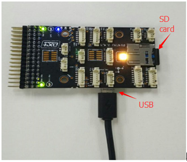
Connect the USB to your PIXHAWK
Load firmware for PIXHAWK
1. Connect PIXHAWK to your computer with a USB cable, open PIX Firmware upgrade application .
Please note: do remember to insert the micro-SD card into the slot at the bottom end of the board before loading firmware to PIXHAW.
2. Click Advanced
3. Select file
4. Choose firmware ArduCopter_V2.px4 to load.
Please note that ArduCopter_V2.px4 should be placed under the directory with an English name.
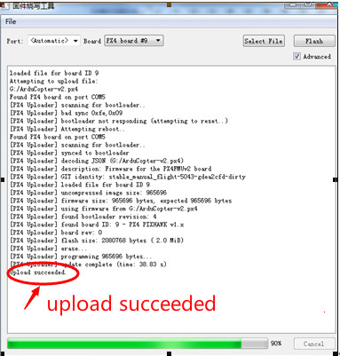
5. After choosing ArduCopter_V2.px4, please click Flash to load.
6. After upload successes, you can close PIX.
Software Setting
The installation of earth station debugging software—Mission Planner
To install Mission Planner, you need the assistance of the plug-in, Net Framework 4. Please download the Net Framework 4.0 and install it first. After the installation of Net Framework 4.0, you can download the Mission Planner Installation Package. (The latest version is recommended)
Note: two different versions, MSI and ZIP are provided on the download page. MSI is an application installation package, PIXHAWK USB driver will be installed together with the Mission Planner, and you can use it with a PIXHAWK USB cable directly.
ZIP is Green Software package, no need for installation. You can use it after unzip. However, you need to install the PIXHAW USB driver manually; the driver program is in the Driver folder. It is up to you to choose your preferred version. But if it is the first time you use it, MSI version is recommended.
Let’s take MSI version as example:
Note: do not connect the PIXHAW USB cable.
Double click the MSI file, then click Next step by step till the Device driver instauration wizard prompts up, click next-continue, or the system will skip the installation of driver.
Notice to read first
When the board is powered with USB, and USB is under connection, PIXHAWK will cut off the communication function of data transmission interface, so please don’t connect data transmission and USB to PIXHAW simultaneously to test PIXHAWK. USB interface is prior than data transmission interface. (USB cable for power supply only is not included here)
As to first-time users of PIXHAWK autopilot, you are advised to get started step by step:
1. Install the ground station controlling software and driver first and get familiar with the menu features on the interface.
2. Learn to download firmware with a USB cable only.
3. Connect the receiver to the PIXHAWK 2.52 board with USB cable to complete the calibrad of remote control, accelerometer and compass.
4. Complete the configuration of all kinds of parameters.
5. Assemble the aircraft and complete the safety inspection, then you can try your first flight.
6. Adjust the PID parameters.
7. All kinds of advanced applications of PIXHAWK.
Instructions on how to use the board
1) Before uploading firmware, you should connect your PIXHAW to the PC with a matching USB cable, make sure the PC has recognized the COM port of PIXHAW, open Mission Planner (hereinafter referred to as MP), the select of COM port is in drop-down box on the upper right corner of the home page of MP, choose the COM port with the identifier of PX4, then set the Baud rate as 115200.
Note: ① Do not click connect button, it will be connected automatically during the process of firmware installation; If you have connected it with PIXHAWK, please do to click Disconnect here or you will receive an error during the installation.
2) Upon uploading a firmware of new version to PIXHAW, there are three things you need to do first:
① calibrate the Radio Calibrad
② calibrate the accelerometer
③ calibrate the compass, the calibration which will affect the unlock process, and red prompts will appear continually on the interface of MP:
3) Install Mission Planner and open it.
Step1. Choose the correct COM port from the drop-down menu for PX4 FMU and set the Baud rate as 115200.
Step2 Click connect icon.
If the connection failed, please check if you cheese the correct COM port, please power off the board and reconnect it.
RC CALIBRATION
1. Calibrate according to the following steps.
Calibrate according to the following steps
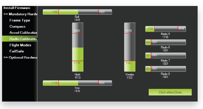
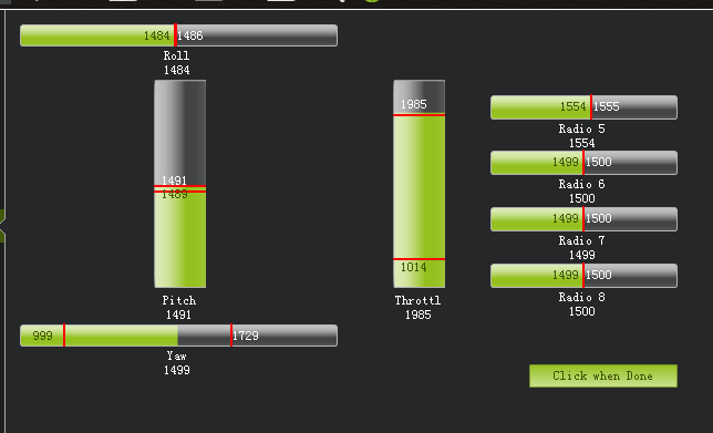
2.Select Radio Calibration to teach Pixhawk to work with your RC transmitter. Turn on your transmitter, select Calibrate Radio, and move all sticks and switches to their extreme positions. Select Click when Done once the red bars are set for all available channels.
3. RC CALIBRATION completed.
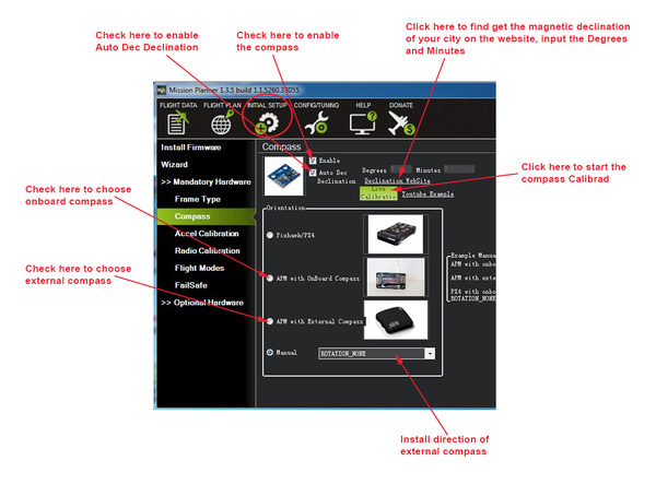
CALIBRATE COMPASS
1. Calibrate according to the following steps.
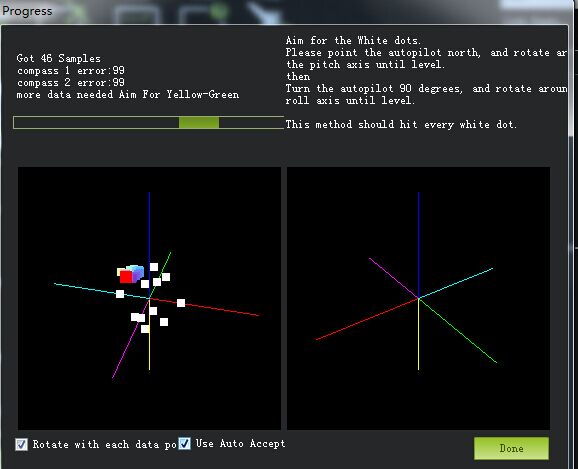
2. Click start calibration and view the window as follow
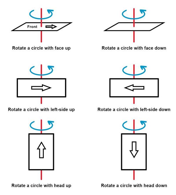
Rotate you PIXHAWK around all axes at least once in 60s until the boxes disappeared. You can refer to the following directions. Data will be collected during the rotate, and the system will record the data collected, the Samples data will accumulate constantly. If the data is not changed, please check if you have connected it correctly.
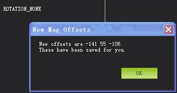
3.A massage box to confirm the data will pop up 60s later; click OK to save the calibration.
Note the three numbers, it is better they are within 255.
Accel calibrate
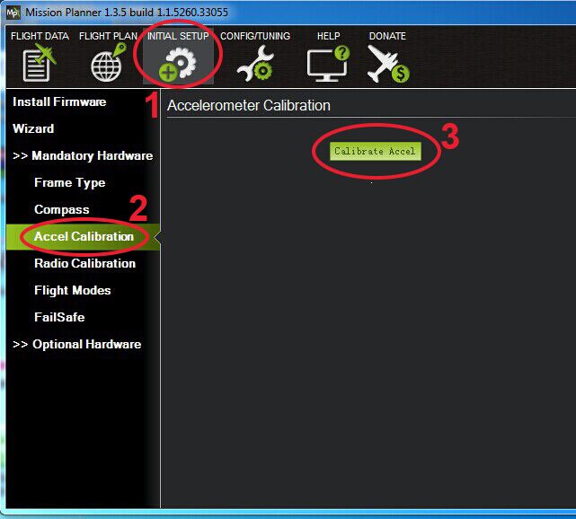
1. The calibration of compass and accelerometer are under the same menu. Click Mandatory Hardware--Install setups—Accel calibrate-- Calibrate Accel.
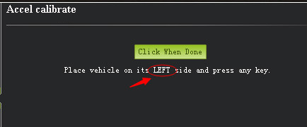
2. Follow the prompts to calibrate Pixhawk’s accelerometer. Make sure to wait a couple of seconds before and after changing the positions of the vehicle.
3. Place the board level and press Enter to change to another position, this is the first movement, do like this for the following positions: Right, Down, Up, Back, and left.
4. If the calibration failed, you can see the following window, you can now disconnect it and reconnect, if it doesn’t work, you can power off the board and try again.
5. If you see this window prompt up, the calibration is successful.

