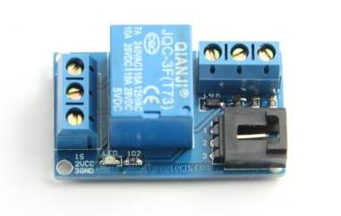
One-Channel Relay module
Introduction
A relay is an electrically operated device. It has a control system and (also called input circuit or input contactor) and controlled system (also called output circuit or output cont actor). It is frequently used in automatic control circuit. To put it simply, it is an automatic switch to controlling a high-current circuit with a low-current signal.
The advantages of a relay lie in its lower inertia of the moving, stability, long-term reliability and small volume. It is widely adopted in devices of power protection, automation technology, sport, remote control, reconnaissance and communication, as well as in devices of electromechanics and power electronics. Generally speaking, a relay contains an induction part which can reflect input variable like current, voltage, power, resistance, frequency, temperature, pressure, speed and light etc. It also contains an actuator module (output) which can energize or de-energize the connection of controlled circuit. There is an intermediary part between input part and output part that is used to coupling and isolate input current, as well as actuate the output. When the rated value of input (voltage, current and temperature etc.) is above the critical value, the controlled output circuit of relay will be energized or de-energized.
NB: input into a relay can be divided into two categories: electrical quantities (including current, voltage, frequency, power etc.) and non- electrical quantities(including temperature, pressure, speed, etc.)
Features
- Number of Relays: 1
- Control signal: TTL level
- Rated load: 7A/240VAC 10A/125VAC 10A/28VDC
- Contact action time: 10ms/5ms
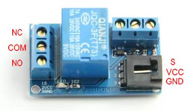
- Module pin definitions: Pin1 - control, Pin3 - ground,Pin2 - VCC
Pin definition
- COM- Common pin
- NC- Normally Closed, in which case NC is connected with COM when S is set low and disconnected when S is high;
- NO- Normally Open, in which case NO is disconnected with COM1 when S is set low and connected when S is high.
Usage
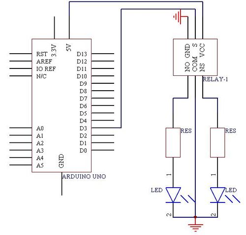
VCC - 5V
GND - GND
S   - Digital pin3
Example code
int Relay = 3;
void setup()
{
 pinMode(Relay, OUTPUT);     //Set Pin3 as output
}
void loop()
{
         digitalWrite(Relay, HIGH);   //Turn off relay
         delay(2000);
         digitalWrite(Relay, LOW);    //Turn on relay
         delay(2000);
}
How to buy
Click here to buy One-Channel Relay module


