Difference between revisions of "One-Channel Relay module"
(→Introduction) |
(→How to buy) |
||
| (13 intermediate revisions by the same user not shown) | |||
| Line 1: | Line 1: | ||
==Introduction== | ==Introduction== | ||
| − | [[File: | + | |
| + | [[File:1 channe relayl preview.jpg|400px|]] | ||
A relay is an electrically operated device. It has a control system and (also called input circuit or input contactor) and controlled system (also called output circuit or output cont actor). It is frequently used in automatic control circuit. To put it simply, it is an automatic switch to controlling a high-current circuit with a low-current signal. | A relay is an electrically operated device. It has a control system and (also called input circuit or input contactor) and controlled system (also called output circuit or output cont actor). It is frequently used in automatic control circuit. To put it simply, it is an automatic switch to controlling a high-current circuit with a low-current signal. | ||
| Line 7: | Line 8: | ||
When the rated value of input (voltage, current and temperature etc.) is above the critical value, the controlled output circuit of relay will be energized or de-energized. | When the rated value of input (voltage, current and temperature etc.) is above the critical value, the controlled output circuit of relay will be energized or de-energized. | ||
| − | + | NB: input into a relay can be divided into two categories: electrical quantities (including current, voltage, frequency, power etc.) and non- electrical quantities(including temperature, pressure, speed, etc.) | |
| + | ===Features=== | ||
The features of 1-Channel Relay module are as follow: | The features of 1-Channel Relay module are as follow: | ||
| + | |||
1) Good in safety. In power system and high voltage system, the lower current can control the higher one. | 1) Good in safety. In power system and high voltage system, the lower current can control the higher one. | ||
| + | |||
2) 1-channel high voltage system output, meeting the needs of single channel control | 2) 1-channel high voltage system output, meeting the needs of single channel control | ||
| + | |||
3) Wide range of controllable voltage. | 3) Wide range of controllable voltage. | ||
| + | |||
4) Being able to control high load current, which can reach 240V, 10A | 4) Being able to control high load current, which can reach 240V, 10A | ||
| + | |||
5) With a normally-open (NO) contact and a normally-closed (NC) contacts | 5) With a normally-open (NO) contact and a normally-closed (NC) contacts | ||
| − | == | + | ===Overview and Hardware Resources=== |
| − | + | ||
| − | + | [[File:11.jpg|700px|]] | |
| − | + | ||
| − | + | One-channel output contact, including a normally-open (NO) contact and a normally-closed (NC) contacts | |
| − | + | ||
| + | One-channel input control (two sets of port) | ||
| + | |||
| + | ==Interfaces == | ||
| + | |||
| + | ===Interface Layout=== | ||
| + | |||
| + | [[File:1 channe relayl intreface.jpg|700px|]] | ||
| + | |||
| + | ===Interface specifications=== | ||
| + | The output contacts of a relay (including NO, NC, and the common port) works as a SPDT – Single Pole Double Throw switch. Its operating principle is as follow: | ||
| + | VCC----5V, | ||
| + | |||
| + | GND----for ground | ||
| + | |||
| + | IN1 connects to the control valve which output 3V-5V | ||
| + | |||
| + | Output contacts: connect to applications | ||
| + | |||
| + | |||
| + | ==Development Environment Setting== | ||
| + | ===Interface Connecting and Setting=== | ||
| + | |||
| + | [[File:1 channe relayl setting 1.jpg|500px|]] | ||
| + | |||
| + | [[File:1 channe relayl setting 2.jpg|500px|]] | ||
| + | |||
| + | ==Get Started== | ||
| + | Firmware resources: Arduino board (any versions), wires, LED, 5v power supply. | ||
| + | Software resource: Arduino IDE | ||
| + | The one-channel relay can be programmed to realize the open and close automatically. | ||
| + | NB: customers can use any software or firmware to control the module as long as the IN1 of which can input a voltage of 3V-5V.you can do further development with the development tool you like as well as test it in the way of testing firmware. | ||
| + | Firmware test: after the connection as in picture1-4, pay attention to the blink of LED, listen to the flicker of relay when it is working. | ||
| + | Software test code: | ||
| + | void setup(){ | ||
| + | pinMode(7,OUTPUT); | ||
| + | } | ||
| + | void loop(){ | ||
| + | pinMode(7,OUTPUT); | ||
| + | delay(2000); | ||
| + | digitalWrite(7,LOW); | ||
| + | delay(2000); | ||
| + | } | ||
| − | + | Feedback of test: after the upload of code, connect the IN1 pins to the 7th pin of Arduino board separately, you can hear the ticktack of the relay (it keeps opening and closing), in addition, the LED-G is blinking every 2s. | |
| − | |||
| − | + | ==FAQS== | |
| − | + | Q1、What’s the maximum load voltage and current of the relay? | |
| − | + | A: The maximum DC load is 10A, the maximum AC load is 7A; the maximum load voltage is 240V. | |
| − | + | Q2:Why is it overheating when the relay is under use? | |
| − | + | A: If the load voltage or current is rather high, it will give off extra heat, it is all right when the temperature is confined within 65℃. You are advised to choose another one that can support larger power if the temperature is upper 65℃. | |
| − | |||
| − | |||
| − | |||
| − | + | Q3: What should I notice when designing or using a relay? | |
| + | A; The relay will discharge spark or magnetic field during the process of mechanical opening and closing. In order to prevent it from being interfered, you’d better keep it away from other MCU or chips. | ||
| − | |||
| − | |||
| − | |||
| − | |||
| − | |||
| − | |||
| − | |||
| − | |||
| − | |||
| − | |||
| − | |||
| − | |||
| − | == | + | ==where to get== |
| − | Click here to | + | Click here to get a 1-channel relay [http://www.geeetech.com/arduino-5v-relay-module-for-your-project-p-245.html One-Channel Relay module] |
Latest revision as of 02:44, 30 July 2014
Contents
Introduction
A relay is an electrically operated device. It has a control system and (also called input circuit or input contactor) and controlled system (also called output circuit or output cont actor). It is frequently used in automatic control circuit. To put it simply, it is an automatic switch to controlling a high-current circuit with a low-current signal.
The advantages of a relay lie in its lower inertia of the moving, stability, long-term reliability and small volume. It is widely adopted in devices of power protection, automation technology, sport, remote control, reconnaissance and communication, as well as in devices of electromechanics and power electronics. Generally speaking, a relay contains an induction part which can reflect input variable like current, voltage, power, resistance, frequency, temperature, pressure, speed and light etc. It also contains an actuator module (output) which can energize or de-energize the connection of controlled circuit. There is an intermediary part between input part and output part that is used to coupling and isolate input current, as well as actuate the output. When the rated value of input (voltage, current and temperature etc.) is above the critical value, the controlled output circuit of relay will be energized or de-energized.
NB: input into a relay can be divided into two categories: electrical quantities (including current, voltage, frequency, power etc.) and non- electrical quantities(including temperature, pressure, speed, etc.)
Features
The features of 1-Channel Relay module are as follow:
1) Good in safety. In power system and high voltage system, the lower current can control the higher one.
2) 1-channel high voltage system output, meeting the needs of single channel control
3) Wide range of controllable voltage.
4) Being able to control high load current, which can reach 240V, 10A
5) With a normally-open (NO) contact and a normally-closed (NC) contacts
Overview and Hardware Resources
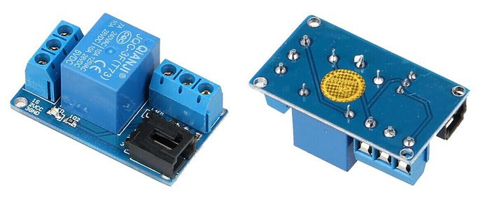
One-channel output contact, including a normally-open (NO) contact and a normally-closed (NC) contacts
One-channel input control (two sets of port)
Interfaces
Interface Layout
Interface specifications
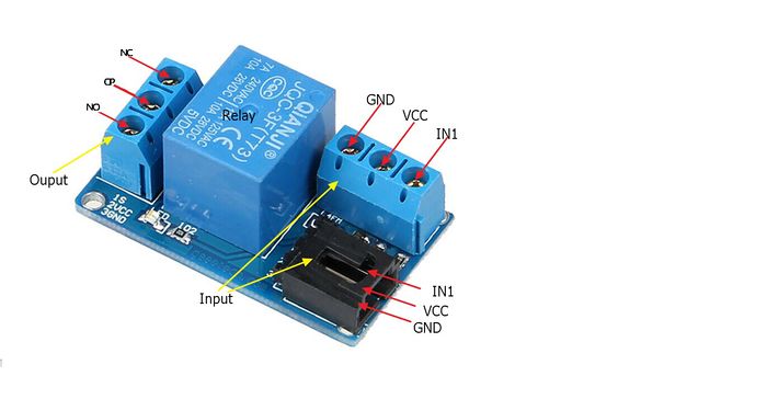
The output contacts of a relay (including NO, NC, and the common port) works as a SPDT – Single Pole Double Throw switch. Its operating principle is as follow: VCC----5V,
GND----for ground
IN1 connects to the control valve which output 3V-5V
Output contacts: connect to applications
Development Environment Setting
Interface Connecting and Setting
Get Started
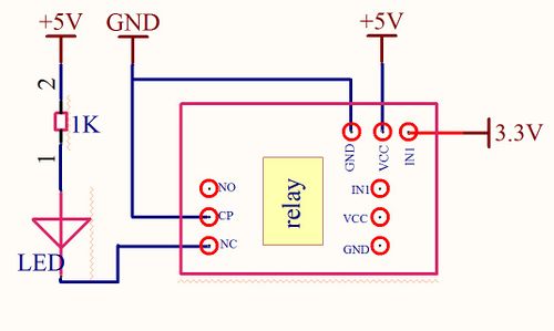
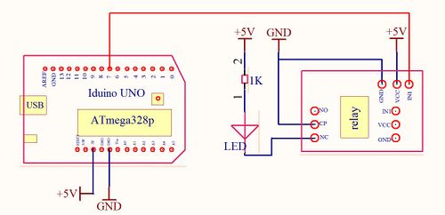
Firmware resources: Arduino board (any versions), wires, LED, 5v power supply. Software resource: Arduino IDE The one-channel relay can be programmed to realize the open and close automatically. NB: customers can use any software or firmware to control the module as long as the IN1 of which can input a voltage of 3V-5V.you can do further development with the development tool you like as well as test it in the way of testing firmware. Firmware test: after the connection as in picture1-4, pay attention to the blink of LED, listen to the flicker of relay when it is working. Software test code:
  void setup(){
   pinMode(7,OUTPUT);
   }
   void loop(){
  pinMode(7,OUTPUT);
  delay(2000);
  digitalWrite(7,LOW);
  delay(2000);
  }
Feedback of test: after the upload of code, connect the IN1 pins to the 7th pin of Arduino board separately, you can hear the ticktack of the relay (it keeps opening and closing), in addition, the LED-G is blinking every 2s.
FAQS
Q1、What’s the maximum load voltage and current of the relay? A: The maximum DC load is 10A, the maximum AC load is 7A; the maximum load voltage is 240V.
Q2:Why is it overheating when the relay is under use? A: If the load voltage or current is rather high, it will give off extra heat, it is all right when the temperature is confined within 65℃. You are advised to choose another one that can support larger power if the temperature is upper 65℃.
Q3: What should I notice when designing or using a relay? A; The relay will discharge spark or magnetic field during the process of mechanical opening and closing. In order to prevent it from being interfered, you’d better keep it away from other MCU or chips.
where to get
Click here to get a 1-channel relay One-Channel Relay module


