MultiWii Multi-Copter Flight Control Board
Contents
Introduction
The Multiwii flight control board is multicopter flight controller board that use Multiwii. MultiWii is a open source software based on Arduino to control a multirotor RC model. After years of joint efforts of many enthusiasts, and now the MultiWii program has become increasingly mature, has become very popular abroad, cost-effective flight control one.
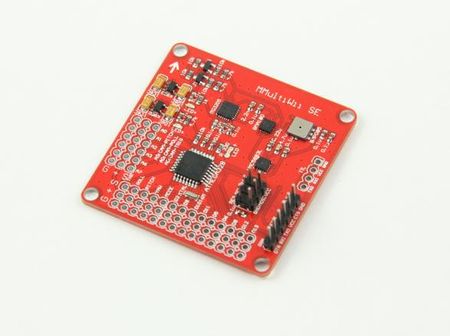
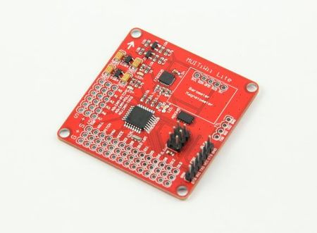
MultiWii SE/Lite above the mainstream hardware platform with a combination of commonly used, which is equivalent to Arduino Pro Mini and 10DOF IMU sensor combined, integrated design makes working more stable flight control. You can use FTDI Basic for easy programming.
Hardware Specification
MultiWii SE Hardware configuration:
- ATMEGA328P microcontroller
- ITG3205 3-axis gyroscope
- BMA180 3-axis accelerometer
- BMP085 pressure sensor
- HMC5883L 3-axis Magnetometer
MultiWii Lite Hardware configuration:
- ATMEGA328P microcontroller
- ITG3205 3-axis gyroscope
- ADXL345 3-axis accelerometer
Features
Multiwii Firmware supports:
- Quadcopter, HexaCopter, Tricoprer, Y6 , Bicopter
- Two Axis Camera Gimbal,
- Acro, Level, HeadFree flying mode
- GPS Hold , GPS Home features with additional GPS module
MultiWii SE/Lite in addition to the necessary input / output ports, but also allow a variety of expansion interfaces, can be used for OSD module, LCD liquid crystal module, Bluetooth module, the data transmission module, GPS module, satellite receiver, 3-axis head and other equipment connection. With Chris MWC LCD module, outside the field can easily adjust the PID parameters, no longer need to carry a laptop computer.
Multiwii GUI operated on Linux/MAC/PC can easily observe the PID parameters, flight control signal input / output status, sensor / switch-state, as well as aircraft attitude and heading sensor signal state of each group, sufficient for the initial configuration of the aircraft easier.
Usage
- Details reference Multiwii main site http://www.multiwii.com/
Copter configuration
- 1. Download and unzip the required software
- -Arduino IDE -use the 1.0 version IDE
http://arduino.cc/en/Main/Software
- -Latest source Code & GUI:
http://code.google.com/p/multiwii/
- 2. Attach the FTDI USB board to the MultiWii SE board and plug in USB cable to PC
- 3. New Hardware dialogs will appear and point to the \drivers\ftdi usb folder in the Arduino folder for the driver. Driver should install and new device be
recognized
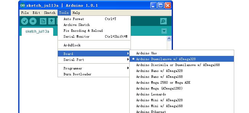
- 4. Set Board type to
- 5. Set Com port to the one the FTDI is on
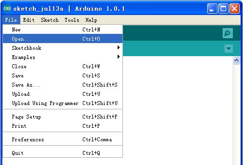
- 6. Open the MultiWii source code
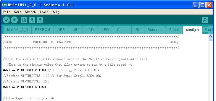
- 7 Select the config.h tab and uncomment (remove “//”) the parameters as below, be sure to comment (“//”) the unused ones in each group
a. Select the Min throttle for your ESCs..this is the lowest value the controller sends to any motor during flight…you want them still spinning at this value or you run out of control.
b. Choose the copter configuration
c. Reverse the yaw sense if needed
d. Use: #define I2C_SPEED 400000L
e. Use: #define INTERNAL_I2C_PULLUPS
f. Use: #define RCAUXPIN8 or #define RCAUXPIN12 if you want to use AUX2 for mode selection in addition to AUX1
- For Lite
Use: #define ITG3205
Use: #define ADXL345
- For SE
Use: #define ITG3205
Use: #define BMA180
Use: #define BMP085
Use: #define HMC5883
g Use: #define MAG_ORIENTATION(X, Y, Z)
{magADC[ROLL] = -Y; magADC[PITCH] = X; magADC[YAW] = Z;}
note this has to beentered manually, not already there but commented out…elsecompass heading is off 90deg
Everything else is left as is….
h.Upload the source code to Multiwii board
GUI configuration
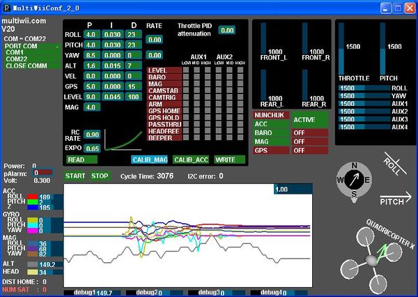
The GUI is a java program that can run on any PC windows/linux/mac computer.The Multiwii board must be connected via an USB cable to the computer to use it.Alternatively, it is possible to use a wireless transmission via bluetooth as data are transported over a simple serial port.
- GUI launch procedure
- You must connect the Multiwii board to your PC via the USB connection and upload the multiwii source code to your board(the same used to inject the software via Arduino IDE)
- Once it’s done, you can launch the GUI, and then select the good PORT COM (the same used by arduino IDE).
- Once it’s done, you have to wait some seconds to let the arduino boot and run the soft. (wait for the LED blink)
- once the status led is OK (it should blink ans stays off), you can press the START button to see the evolution of values.
- you must READ the current parameters in the Arduino before configuring it. Default values are set at the beginning.The default values can be reset by uploading an old version and then the last version.
Parameter explanation
(taken from Multiwii.com):
- RC rate and RC expo
RC rate: defines the sensibility of the multicopter for PITCH and ROLL RC stick. If you feel your multi too reactive, decrease it. If you want to improve its responsiveness, increase this parameter.
RC expo: defines a smoother zone at the center of PITC and ROLL RC stick. With this function, it’s possible to have both a good precision and a good amplitude.
0 = no expo
1 = full expo
If you don’t understand really those parameters, I encourage you to read your TX documentation, as those functions are also generally suported by the TX.It’s better to support them directly in multiwii because the resolution is better this way.
- P and I Level
Defines the acc influence in stable mode only (this parameter has no effect if the stable mode is disable) If the multi is not stable once activated, reduce P.
- PITCH/ROLL/YAW PID and rate
For a very stable multicopter with a solid attitude, the PID settings must be set high. But if you want to do some acrobatics with these settings, the multi starts to wobble in fast translation or when you decide to shake it to much. One solution is to decrease the PID, but it is to the detriment of static stability.
So instead of implementing a switch between 2 PID settings, there are now 2 options in the GUI to define the way we should decrease PID, depending on ROLL/PITCH/YAW stick deviation
The two boxes on the right defines the rate of cancellation of the nominal PID (the one which is used on neutral ROLL/PITCH/YAW stick position) in relation with ROLL/STICK/YAW deviation. In fact only P and D parameters are impacted in the transformation. The purpose of this setting is not really to gain more stability, but to gain more maneuverability. 0 = soft rate (for FPV or beginners); 0.4 = soft acro ; 0.7 = fast acro ; 1 = insane rate If you are not familiar with this, just keep the default values (0)
- THROTTLE rate
This boxe defines the rate of cancellation of the nominal PID (the one which is used on neutral ROLL/PITCH stick position) in relation with Throttle stick.
The purpose of this curve is to gain more stability when you are in a situation to use more throttle than needed to just maintain a lift. This is typically the case in fast translation.
If you are not familiar with this, just keep the default values (0)
- How to activate options
Depending on your configuration, you can easily activate/deactivate options via 2 switches on your RC TX.
The 2 switches correspond to channel 5 (AUX1) and channel 6 (AUX2).
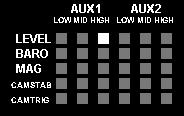
LEVEL is the autolevel feature (require an ACC)
BARO allows to keep a constant altitude once activated (require a barometer)
MAG allows to keep a perfect heading direction once activated (require a magnetometer)
CAMSTAB: if activated, the PITCH&ROLL servo output will follow the inclination of the multi (require an ACC + the code activation via #define statement)
CAMSTRIG: if activated, a servo output will trigger repetitively a sequence where we can define the duration on the HIGH/LOW position.
To activate a function, you must check the white box at the intersection of the required option (row) and at the switch state you want to enable (column).
It’s possible to make a complex mix.
If you want to force an option permanently, it’s possible to check all the white boxes, even without a RC channel connected.
(=> this way, you don’t need a 5 or 6 channels RC receiver)
- Sensor detection/usage
On this screen, the left column resumes the detection of sensors.
The right column precises if the sensor is currently use or not (depending on the checked options)
Hardware Setup
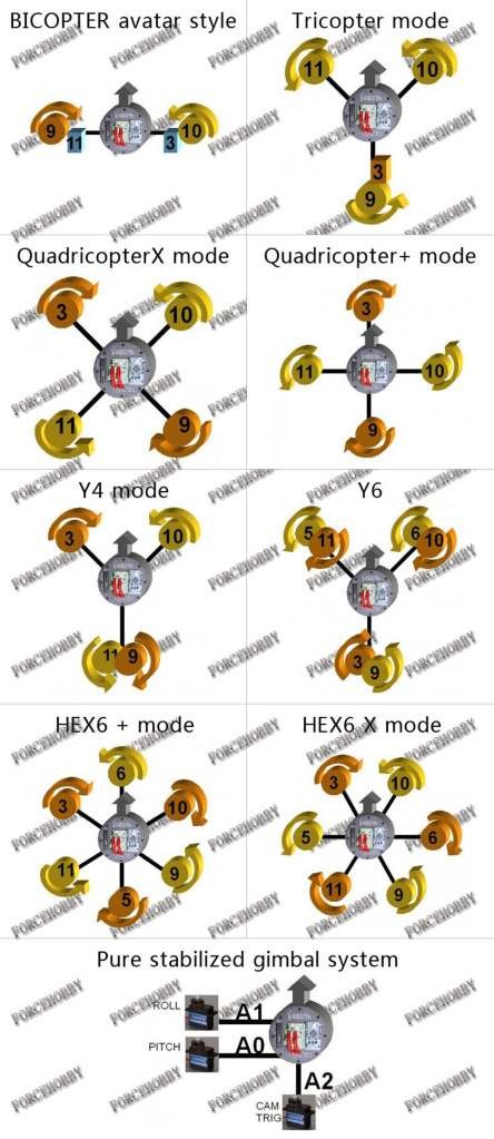
- Motor connections and rotations are shown below
Numbers refer to pins D3,9,10,11,5,and D6 above…the Motor1-6 ESC outputs.
Note: if the ESC uses a LINEAR BEC, you can connect all to the motor outputs
without modification. If the BECs are switching types, you should use only one
BEC output and remove the red wires from the other ESC connectors.
Alternatively, all can be removed and an External BEC connected to D13, A6,
or A7 or any unused three pin connection.
- BALANCE PROPS and MOTORS!
- Check that all TX channels are centered at 1500 and run from 1000 to 2000.
- Check that all channels are correct direction…ie right runs right on roll, etc., if not reverse them.
- Calibrate Gyro (board not moving!)
- Calibrate Accelerometers (board level!)
- Calibrate Magnetometer:
press Calib_Mag - the LED blinks rapidly -you have 30secs to rotate the board 360°degress in all axis X, Y and Z - when the LED stops blinking it will save all the MAG tilt errors to eprom. - Set ESC ranges:Individually connect escs to RX throttle channel and follow ESC manual directions for setting min/max throttle range.
- Fly, trim with autolevel off, adjust PIDs IF necessary…small changes, one ata time!
- Set autolevel on and trim using stick commands to get drift free autolevel;adjust PIDS, if necessary.
- Set altitude on and adjust PIDS for heading hold, if necessary
PID Tuning
the default PID values should get almost all normal sized multi copters up &
flying pretty good.
P: 4
I: 0.035
D: -15
Further tuning is mostly done by just lowering / raising the P value.
In order to fine tune, ….. increment/decrement the values with the following
steps: P:0.2 ; I:0.005 ; D:1
"P" fights all motion... increase until you get a feedback wobble, reduce by ~20%
"I" is heading hold.... increase until you get a bounce back when you release a big stick input.
"D" the bigger the better from what I can tell this tries to smooth out any rotation. The higher you run "D" it appears you can further increase "P"
"D" the bigger the better… to smooth out any rotation. The farther from zero you run "D" it appears you can further increase "P"
Some recommend tuning P first, then D, then I.
How to buy
Click here to buy MultiWii SE
Click here to buy MultiWii Lite
