Re: Won't auto-home at Z axis
Posted: Sun Apr 12, 2020 11:15 pm
Alright, thanks to the Easter holidays I was able to find the error and fix it. So the solution is:
1. Open up your printer and change the Z-endstop cables to the one unused. This means change the cable, initially on the red circle (see below) to the yellow one.

2. Download the Marlin firmware. I got the latest version (v2.0.5.3) and it is working fine, no issues whatsoever of having to reset when uploading. I use Arduino IDE to upload the Marlin.ino file. Make sure that in the "configuration.h" file, you are using the GT2560 V3 board. Eventhough we have the GT2560 V4, it seems the pins are connected to the same ATMEGA2560 ports on both.
#ifndef MOTHERBOARD
#define MOTHERBOARD BOARD_GT2560_V3
#endif
3. Now it seems that the logic pin for this extra switch is connected to the physical pin 9/PE7/INT7 in the ATMEGA2560. See image below. This is confirmed since I proved it with the multimeter.
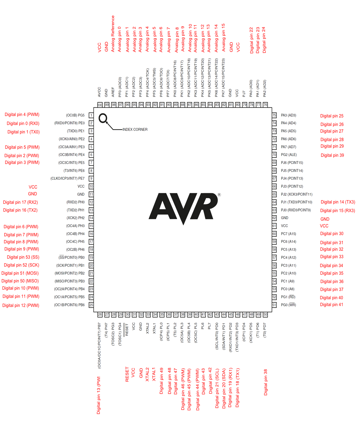
The easiest is to change the file found in "...\Marlin\src\HAL\AVR\fastio\fastio_1280.h" to change the faulty pin for the unused one, which is not even included in the "fastio_1280.h" file. You can see it is unused on the above image. So, to put it simply, change these original lines of code in the file "fastio_1280.h":
#define DIO30_PIN PINC7
#define DIO30_RPORT PINC
#define DIO30_WPORT PORTC
#define DIO30_DDR DDRC
#define DIO30_PWM nullptr
For these ones:
#define DIO30_PIN PINE7
#define DIO30_RPORT PINE
#define DIO30_WPORT PORTE
#define DIO30_DDR DDRE
#define DIO30_PWM nullptr
And then just upload your firmware and you are all set. This worked for me.
Good luck !
1. Open up your printer and change the Z-endstop cables to the one unused. This means change the cable, initially on the red circle (see below) to the yellow one.
2. Download the Marlin firmware. I got the latest version (v2.0.5.3) and it is working fine, no issues whatsoever of having to reset when uploading. I use Arduino IDE to upload the Marlin.ino file. Make sure that in the "configuration.h" file, you are using the GT2560 V3 board. Eventhough we have the GT2560 V4, it seems the pins are connected to the same ATMEGA2560 ports on both.
#ifndef MOTHERBOARD
#define MOTHERBOARD BOARD_GT2560_V3
#endif
3. Now it seems that the logic pin for this extra switch is connected to the physical pin 9/PE7/INT7 in the ATMEGA2560. See image below. This is confirmed since I proved it with the multimeter.
The easiest is to change the file found in "...\Marlin\src\HAL\AVR\fastio\fastio_1280.h" to change the faulty pin for the unused one, which is not even included in the "fastio_1280.h" file. You can see it is unused on the above image. So, to put it simply, change these original lines of code in the file "fastio_1280.h":
#define DIO30_PIN PINC7
#define DIO30_RPORT PINC
#define DIO30_WPORT PORTC
#define DIO30_DDR DDRC
#define DIO30_PWM nullptr
For these ones:
#define DIO30_PIN PINE7
#define DIO30_RPORT PINE
#define DIO30_WPORT PORTE
#define DIO30_DDR DDRE
#define DIO30_PWM nullptr
And then just upload your firmware and you are all set. This worked for me.
Good luck !