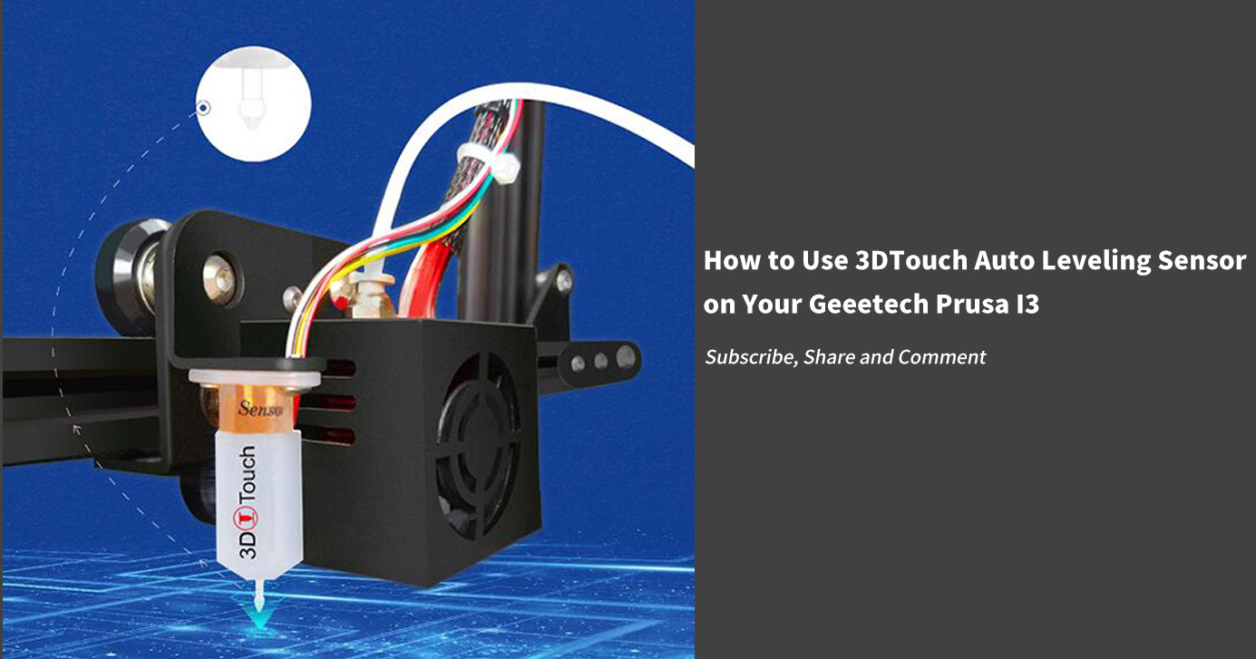
How to Use 3DTouch Auto Leveling Sensor on Your Geeetech Prusa I3
3DTouch is an auto leveling sensor for 3D Printers that can precisely measure the tilt of your print surface. It can greatly improve the printing precision of your 3D Printer. 3DTouch features simple, smart and precise. It could work with nearly any kind of bed materials, such as glasses, woods, metals and so on.The main functions and controls of 3DTouch are the same as most auto bed leveling sensors, which consists of a RC servo and a micro switch, thus, 3DTouch can be used on almost every 3D printer control board.
Geeetech 3D Touch uses to Hall-effect sensors. Hall effect sensors have been used in various industries. Its basic function is to determine the proximity of objects through a static magnetic field. This technology mainly uses magnets to extend and retract for positioning to detect the distance to the print bed. The data read by the printer is converted from analog readings into numbers by sensors.
Common leveling sensors and probes used in 3D printer beds also include induction probes, capacitive, micro switches (physical end stops), infrared, and optical sensors.
How to use it?
1. mount the 3DTouch sensor
So far we have successfully tested our 3DTouch sensor on Geeetech Prusa I3 pro B, Pro C, and Pro X. Here are detailed instructions on how to use the 3DTouch sensor on your geeetech pro B. For pro C and pro X, the steps are the same. You will need a suitable mount to attach the 3DTouch sensor to your printer. Here is a 3DTouch sensor mount:
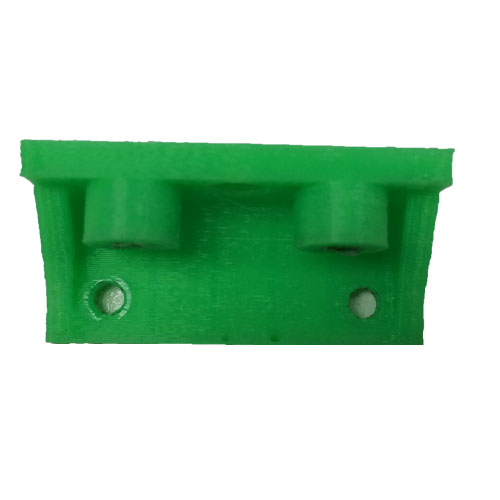
(1) Download the .stl file here and print one.
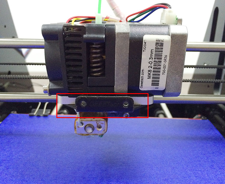
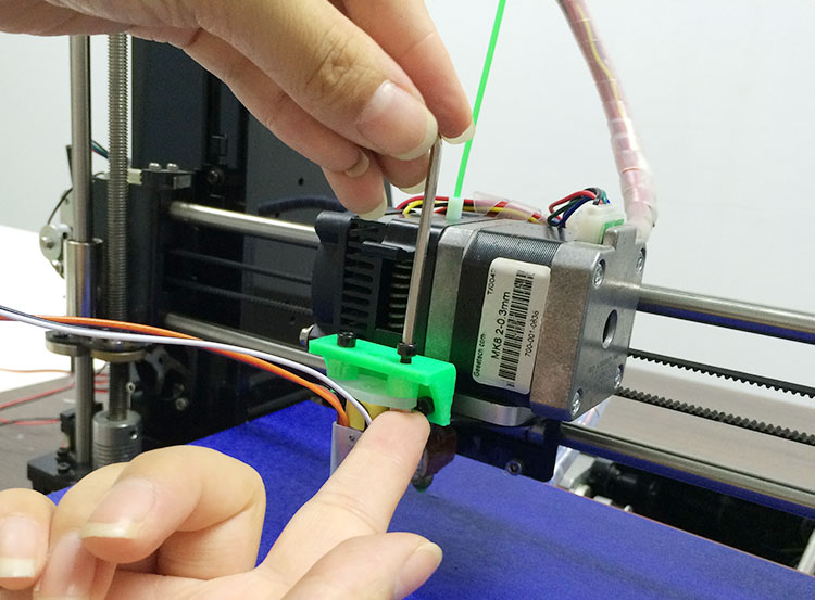
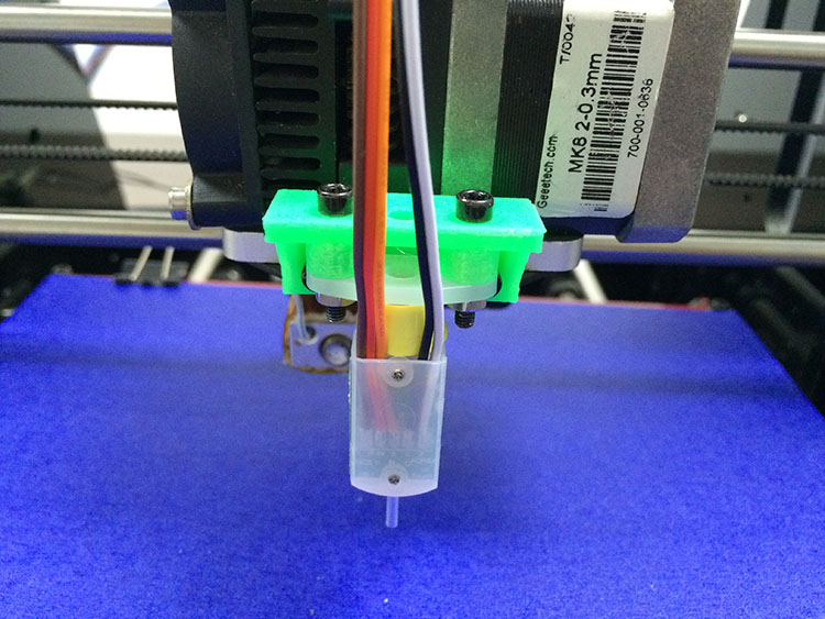
(2) Fix the mount on the Extruder holder with 2 M3*6mm screws.
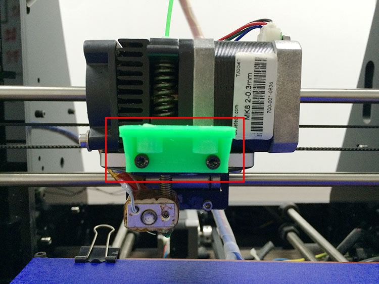
(3) Fix the 3DTouch sensor on the sensor mount with 2 M3*16mm screws and 2 M3 nuts.
2. Wiring
The 3DTouch Auto Leveling sensor has 5 wires, 3 for the first servo connection and 5v and 2 for the Z min end stop, negative, and signal pins.
3DTouch can be operated in the following conditions.
(1) One I/O for control (PWM or Software PWM)
(2) One I/O for Z min (Z Probe)
(3) GND and +5V power
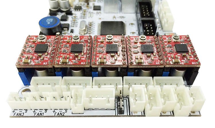
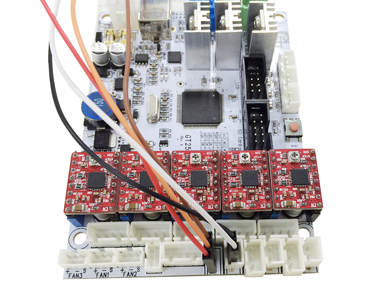
Let’s take our geeetech GT2560 3D Printer control board as an example. There are several ways to connect the 3DTouch Auto Leveling sensor to GT2560, here is the easiest way.
Step 1. Remove the Z max connector from the board and replace it with a 3Pin Straight Pin. You need to use a soldering iron here.
Step 2. Use DuPont wire to extend the wires of 3DTouch. It doesn’t matter if you cannot find the wires with the same color, but do not mix the wires up.
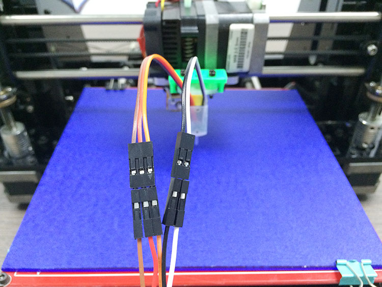
Step 3. Connect the extended wire to the GT2560 control board.
Connect the 3 pin wire to the Z max pin.
3-pin: Brown (-, GND) Red (+5V) Orange (control signal)
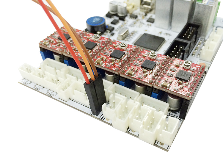
Connect the 2-pin wire to the Z min pin.
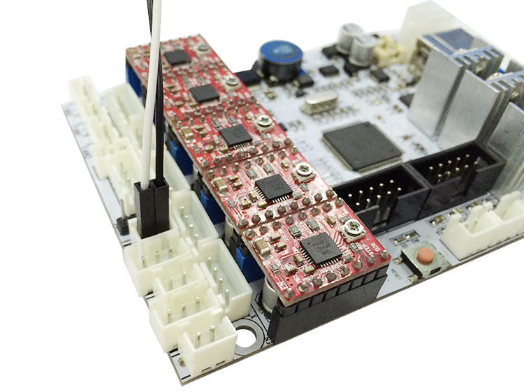
Note the wire order. When using 3DTouch Auto Leveling sensor, you do not need to connect the original Z min end stop wires.
That’s all for the wiring of the 3DTouch Auto Leveling sensor and GT2560.
3. Firmware setting
Changes need to be made to the configuration file in the Marlin source code for 3DTouch. The required changes are similar to how you would set up a mechanical servo sensor.
Step 1. Find the following code in Configuration.h:
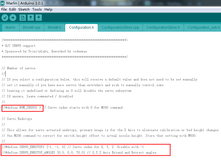
- Modify the code in the red box into:
- // Number of servos
- //
- // If you select a configuration below, this will receive a default value and does not need to be set manually
- // set it manually if you have more servos than extruders and wish to manually control some
- //Leaving it undefined or defining it as 0 will disable the servo subsystem
- // If unsure, leave commented / disabled
- //
- #define NUM_SERVOS 1 // Servo index starts with 0 for M280 command
- // Servo Endstops
- //
- // This allows for servo-actuated endstops, primary usage is for the Z Axis to eliminate calibration or bed height changes.
- // Use the M206 command to correct for switch height offset to the actual nozzle height. Store that setting with M500.
- //
- #define SERVO_ENDSTOPS {-1, -1, 0} // Servo index for X, Y, Z. Disable with -1
- #define SERVO_ENDSTOP_ANGLES {0,0, 0,0, 10,90} // X,Y,Z Axis Extend and Retract angles
Step 2. Find the codes regarding Bed Auto Leveling in Configuration.h.
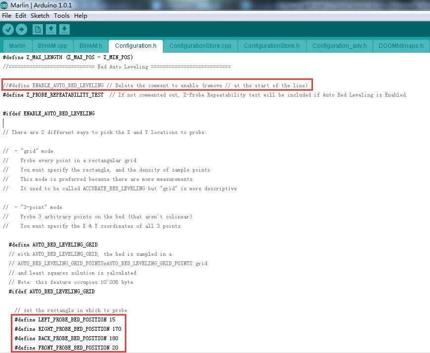
//=============================Bed Auto Leveling=======================
- #define ENABLE_AUTO_BED_LEVELING // Delete the comment to enable (remove // at the start of the line)
- #define Z_PROBE_REPEATABILITY_TEST // If not commented out, the Z-Probe Repeatability test will be included if Auto Bed Leveling is Enabled.
- #ifdef ENABLE_AUTO_BED_LEVELING
- …
- #define AUTO_BED_LEVELING_GRID
- …
- #ifdef AUTO_BED_LEVELING_GRID
- //Set the rectangle in which to probe
- #define LEFT_PROBE_BED_POSITION 30
- #define RIGHT_PROBE_BED_POSITION 200
- #define BACK_PROBE_BED_POSITION 147
- #define FRONT_PROBE_BED_POSITION 20
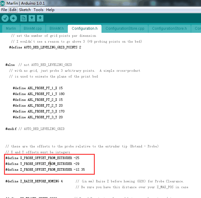
- Step 3: scroll down to find the codes to Define the probe offset
-
#define AUTO_BED_LEVELING_GRID_POINTS 2
#else // not AUTO_BED_LEVELING_GRID
#define X_PROBE_OFFSET_FROM_EXTRUDER 6
#define Y_PROBE_OFFSET_FROM_EXTRUDER -43
#define Z_PROBE_OFFSET_FROM_EXTRUDER -1.4
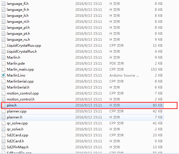
Step 4. Find the following code in pins.h
If you do not find the pins.h tab on Arduino IDE, please open it separately, after the modification, please save it.
-
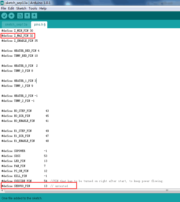
Find the code as shown in the red box:
/*****************************************************************
* Ultimaker pin assignment
******************************************************************/
#if MB(ULTIMAKER)
#define KNOWN_BOARD
#define Z_MAX_PIN -1//32
#define Z_ENABLE_PIN 35
#define SUICIDE_PIN 54 //PIN that has to be turned on right after start, to keep power flowing.
#define SERVO0_PIN 32//13 // untested
Now, that we have finished the firmware; please upload the modified firmware to your control board.
4. Testing
When the 3DTouch is first powered up it does a self-test – Starting with the pin-up it then goes down/up 3 times and ends up with the LED on solid. Continuous flashing means that there is an obstruction or fault.
The 3DTouch acts on the following g.code that can be used manually to diagnose faults etc but you don’t need to normally worry about them.
M280 P0 S10 ; pushes the pin down
M280 P0 S90 ; pulls the pin-up
M280 P0 S120 ; Self-test – keeps going until you do pin up/down or release alarm
M280 P0 S160 ; Release alarm
Alarm – The 3DTouch can sense when something is wrong and then goes into alarm mode which is continuous flashing. The alarm can be triggered like an obstruction that stops the pin from going up and down freely, it could be dirt, etc.
5. Printer Setting
Providing the firmware is correctly configured, the sensor responds to the same codes as any other sensor e.g. inductive, capacitive, or IR. The Start Code in your slicer should contain the sequence G28 followed by G29 to do the auto bed leveling.
Open Slicer>printer setting
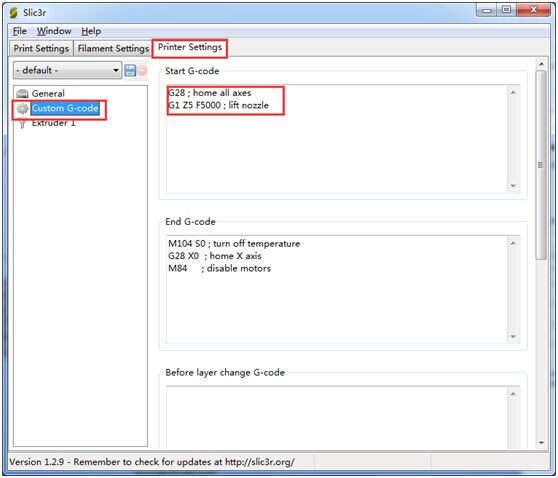
Add G29 command right after G28
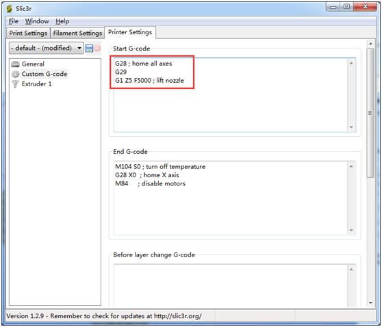
*Don’t put another G28 after the G29 as it will just remove the G29 results.
The G29 command should be added every time.
Here is a video of using the 3DTouch Auto Leveling Sensor on Geeetech Prusa I3 pro B 3d printer.
For more information about 3DTouch auto-leveling sensor, you can also refer to
3D Touch: The REAL Hands-free Levelling Accessory