Create your own electrostatic motor using a 3D printer
Today we share a tutorial about how to use your 3D printer create a electrostatic motor.
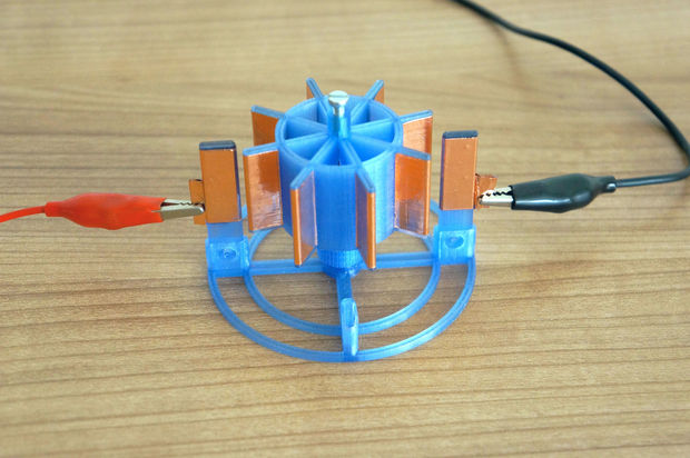
3D printed electrostatic motor
Goal: No ball bearings, easy mounting, new different design with low power requirements
Requires:
1x 3mm screw about 10mm long e.g. unused screw from old PC hardware
1x 50 mm wire ~0.5-1mm e.g. paperclip
1x aluminium foil or copper foil e.g. self-adhesive aluminum tape for sealing or plain foil to glue
1x HV power source e.g. Wimshurst, Van-de-Graaff, Flyback Transformers
3D printed parts:
558.384 base.stl
58.984 electrode.stl – you need at least two printed
287.884 rotor.stl
258.384 screw_top.stl – to fix the wire for the rotor
All files netfabb checked
Step 1: Assembly
Print the parts on your 3D printer – i used 100% infill and only standard settings, no support required
Electrode.stl has to be printed twice. But you can use up to four electrodes with this design
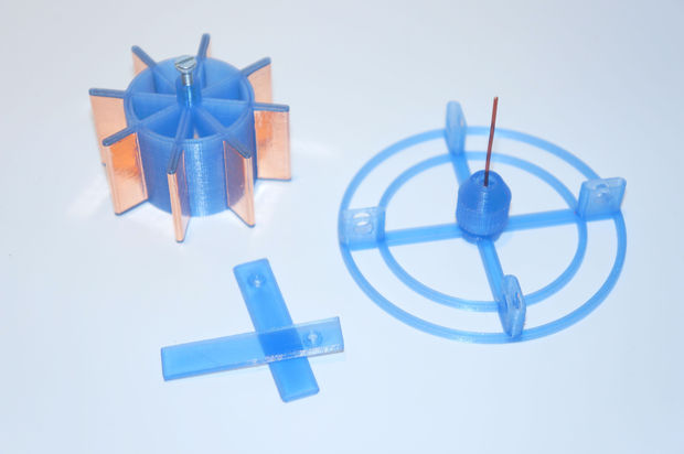
First add the copper or aluminium foil to the rotor and the electrodes as shown in the picture
The electrodes have a sharp edge at one side which will only fit in one direction to the base – towards the rotor blades. The rotor blades need also be covered with foil because it will receive the charge from the electrodes.
When you have glued or used self-adhesive foil for the eight motor blades and at least two electrodes you
can add a piece of wire ~ 50 mm long e.g. the bigger paper clips. The wire has to be strong enough to hold the rotor in place and goes into the middle hole of the base. It will not fall through – just put it in and then take the screw_top.stl (alias the nut) printed part and screw (press fit by closing the screw) it together with the base to fix the wire.
Put the rotor on the wire so the small cylinder of the rotor is on the top side and the wire goes through
Cut the wire just above it is visible from the rotor and then add the 3mm screw to adust the height about the base.
Finally clip the electrodes into the slot you want e.g. 180° opposite from picture or 90° works too.
Attach your HV power source to the electrodes.
This article published by the joehan on instructables, thanks joehan’s sharing.