Assembly manual of Hexypider— the Hexapod
In my last post, i have introduced the Hexypider for you and some are asking for the assembly manual, ok, let’s check together.
we will take one leg firsto assemble , let’s have a look at the parts needed.
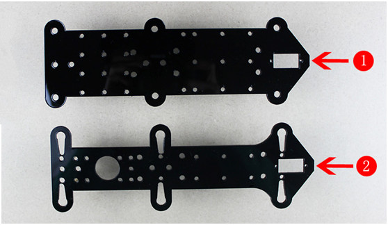
1, the main body of the robot is two pieces of acrylic plate.
Part 1: acrylic sheet on the bottom x 1
Part 2: acrylic sheet on the top x 1
2,The hardware needed to assemble the Hexapod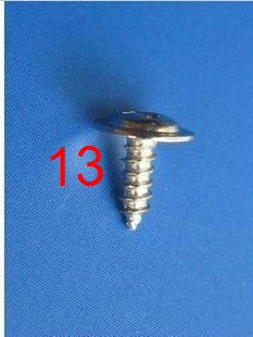
Part3: brass straight pin M3 40mm x 5
Part4: sink head screw M5 10mm x 6
Part5: round head screw M3 12mm x 6
Part6: round head screw M3 10mm x 34
Part7: round head screwM1.5 11mm x 18
Part8: round head screwM2 7mm x24
Part9: screw nut M5 x 6
Part10: screw nut M3 x 34
Part11: screw nut M1.5 x 18
Part12: Servo fittings x 12
Part13: self tapping screw M2 9mm x 6 (with washer)

3 ,Other acrylic supporting components
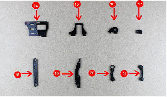
Part 14:Acrylic fitting x 6
Part 15:Acrylic fitting x 6
Part 16:Acrylic fitting x 6
Part 17:Acrylic fitting x 6
Part 18:Acrylic fitting x 3(on the top)
Part 19:Acrylic fitting x 6
Part 20:Acrylic fitting x 6
Part 21:Acrylic fitting x 6
Ok , now we can move on to the assembly procedure
Step 1
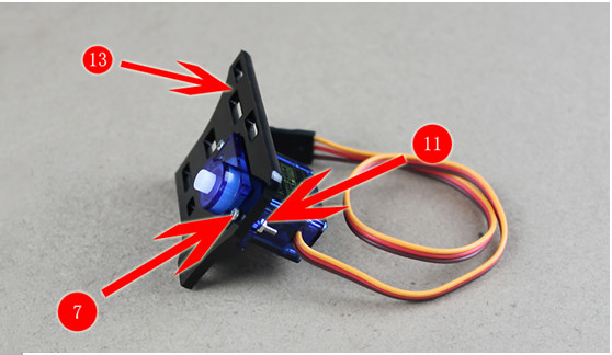
Take the part 13; fix the Servo in part 13 with a screw (part7) and screw nut (part11), as shown in the picture;
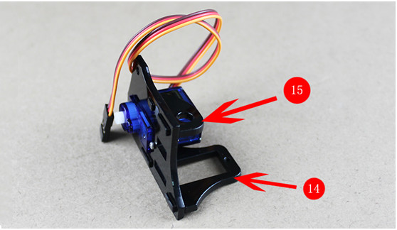
Step 2
Take out part14 and 15, mount them in to part 13(plug slightly, do not force too much, or the acrylic part will be broken.) as shown in the picture;
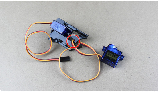
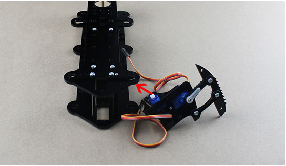
Step 3
Take out another servo; thread the wire of servo through the hole on part 13.
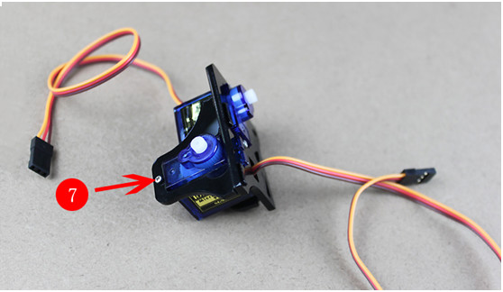
Step 4
Fix the servo on part 13with a pair of screw (part 7) and screw nut (part 11).
Step 5
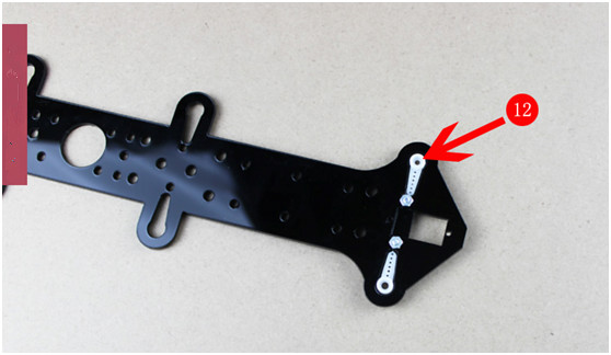
Insert part 12 into part 19.
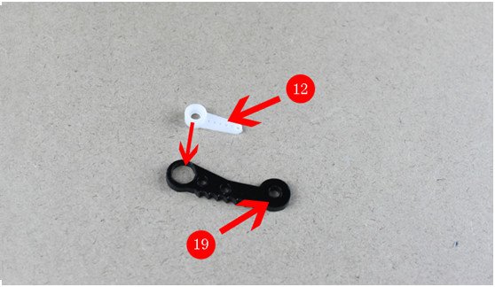
Step 6
Screw up part 12 and 19 with a round head screw (part8),
Step 7
Take out part 20 and 18; screw up part 20 and the assembled part in the above step on part 18 with two round head screws (part 6).
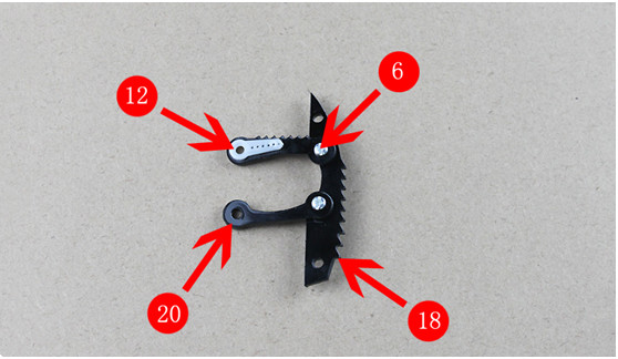
Step 8
Tighten the part finished in step 7 up on the part finished in step 4.

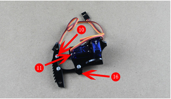
Step 9
Block up the rocker arm with part 16; screw it up with part 10 and 11, assemble the rest arms in the same way.
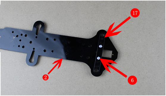
Step 10
Tighten part 17 up on part 2 with a pair of screw and screw nut (part 6). Assemble the rest 2 part 17 on the acrylic sheet in the same way.
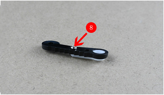
Step 11
Insert the white part (the servo fittings) into the following place. Screw them up with a round head screw (part 8).
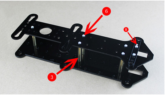
Step 12
Connect the top and bottom main body sheet with 5brass straight pins(part 3) round head screws(part6).
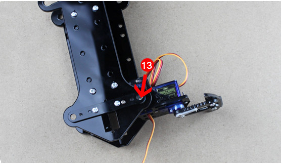
Step 13
Fix the “leg” assembled in step 9 on the following place (showing with the red arrow) with a self-tapping screw (part 13).
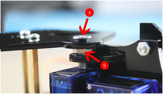
step14
Fix the servo up with a sink head screw and a screw nut to ensure the stability of the servo. So far we have finished a “leg”; you can assemble the rest legs according to the above steps.
Assemble the followint legs in the same way, and your Hexypider should look like this one.
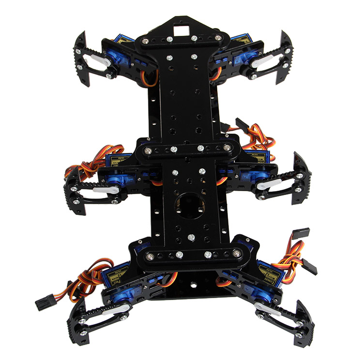
Here you can get a set of the Hexipider. Good luck!